
Salus Hydraulics · documentation and technical support
Cartridge valves — functions, cavities and documentation
Documentation is organised by cartridge valve family and function. Find the full designation, then compare the hydraulic symbol, cavity and actuation method. Similar names or threads do not establish interchangeability between different designs.
Our store has its own language selector. Choose English in the store if needed. For a delivery enquiry, include your destination country and postcode.
Manufacturer documents are provided in their original language; the language may vary by file. Series-level ratings are a guide: check the exact model and operating conditions in its data sheet.
Legacy Eaton / Vickers names remain in some catalogues and nameplates. Check current product information in Danfoss PowerSource and compare the complete part number. A brand-name change alone does not confirm interchangeability.
Looking for a part by its code?
Choose a manufacturer. These indexes connect part references with PDF documentation, selection guidance and matching store listings.
From documentation to a specific part
Use the links below to compare documentation with specific store listings. A series catalogue covers multiple configurations: confirm the full code, document revision and electrical options before ordering. Current prices and availability are shown in the store.
- HydraForce FR50-28A-0-N
FR50-28 series catalogue (PDF) · View this part in the store
HydraForce and Danfoss / Eaton / Integrated Hydraulics cartridge documentation
HydraForce cartridge valves — series and configurations
HydraForce documentation covers cartridge valves, housings and hydraulic manifolds. Start with the hydraulic function and full part number, then check the cavity, actuation and operating limits for that configuration. For manifold selection, send us your circuit diagram and machine requirements. See hydraforce.pl for additional references and the HydraForce manufacturer website for current product and design resources.
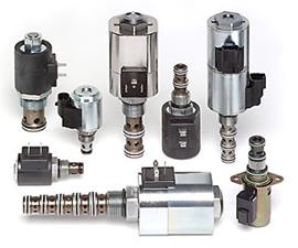
HydraForce solenoid valves
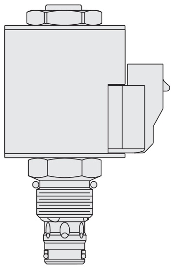
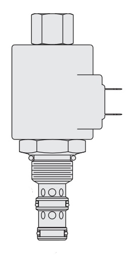
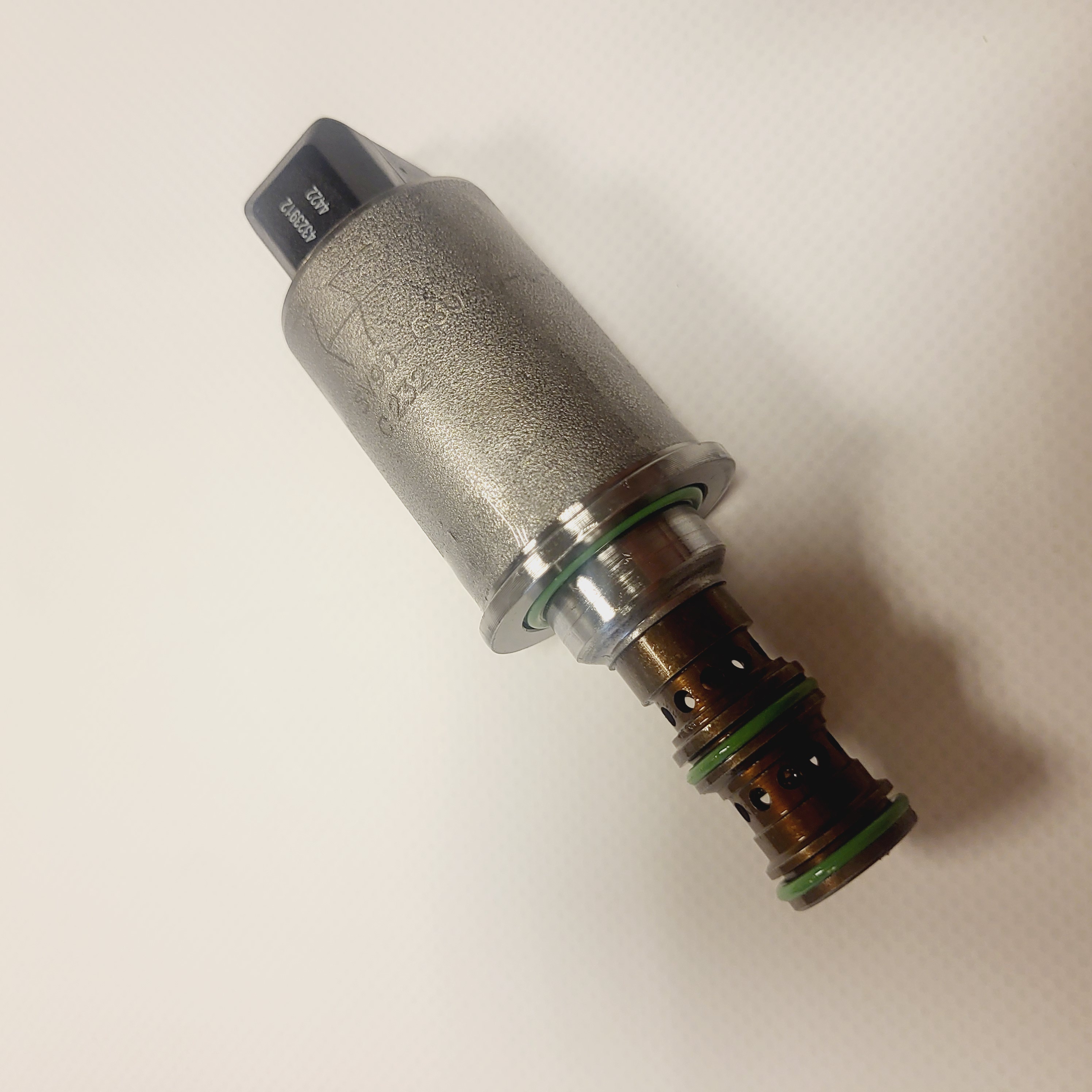
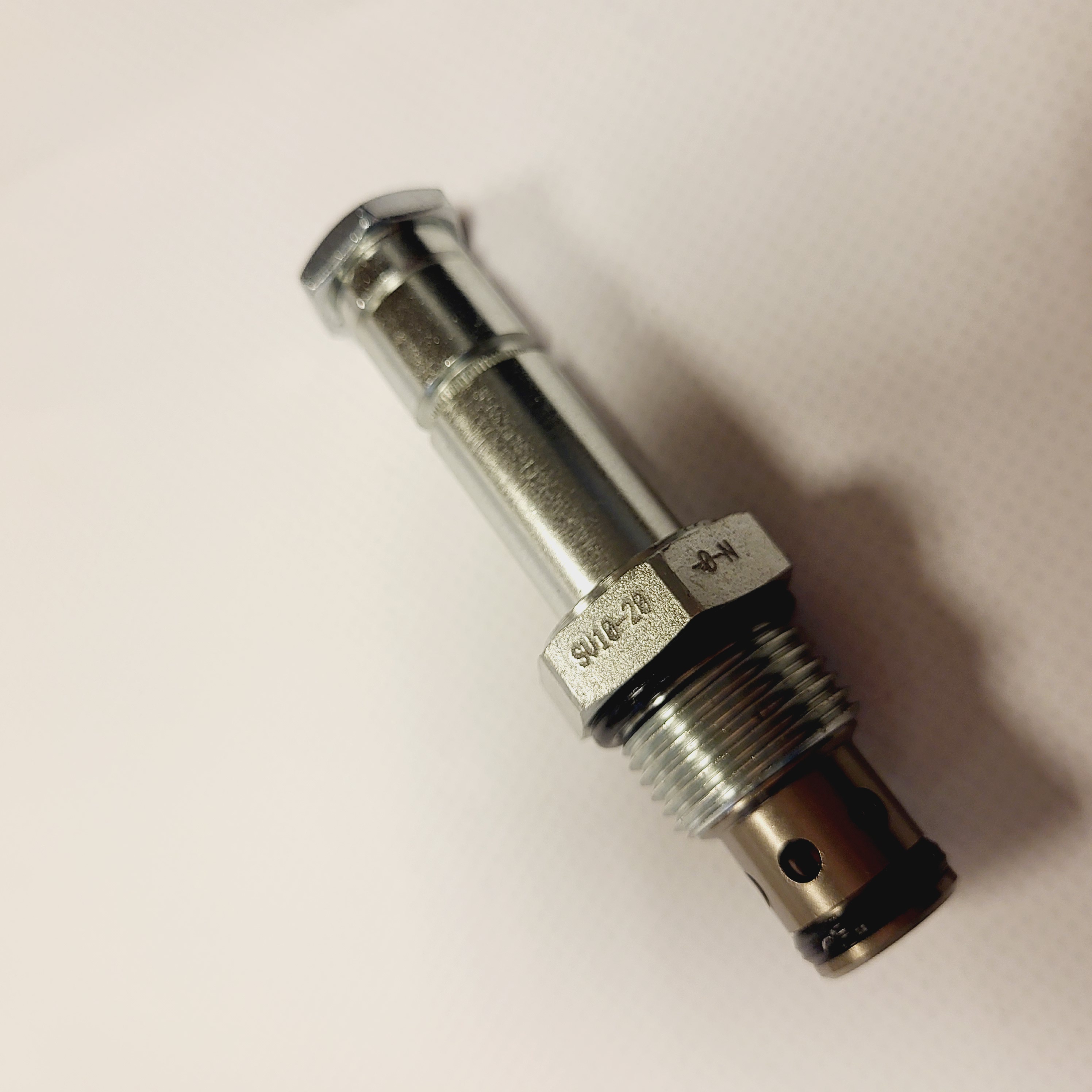
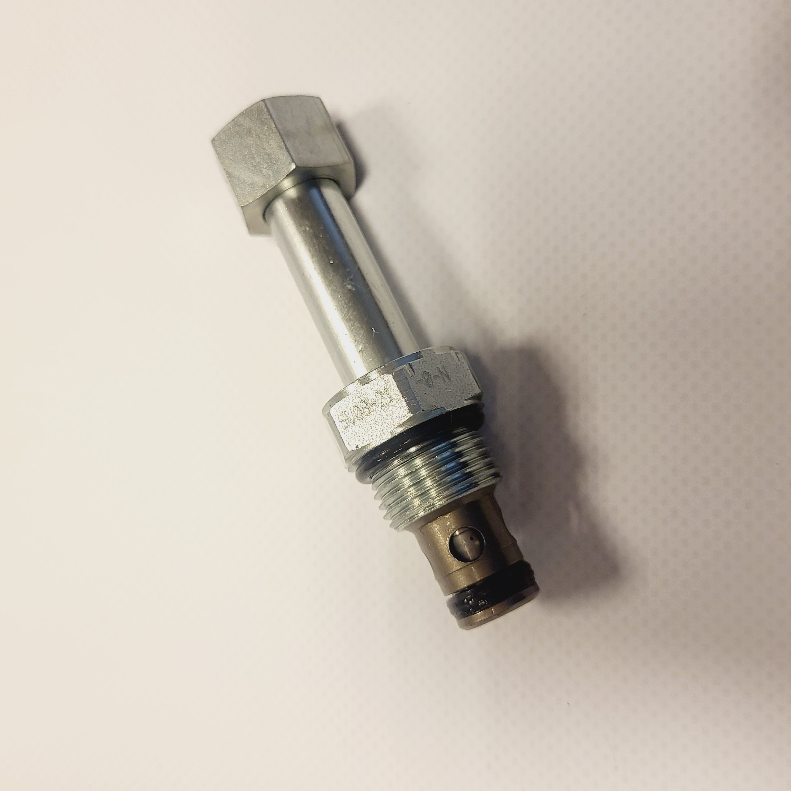
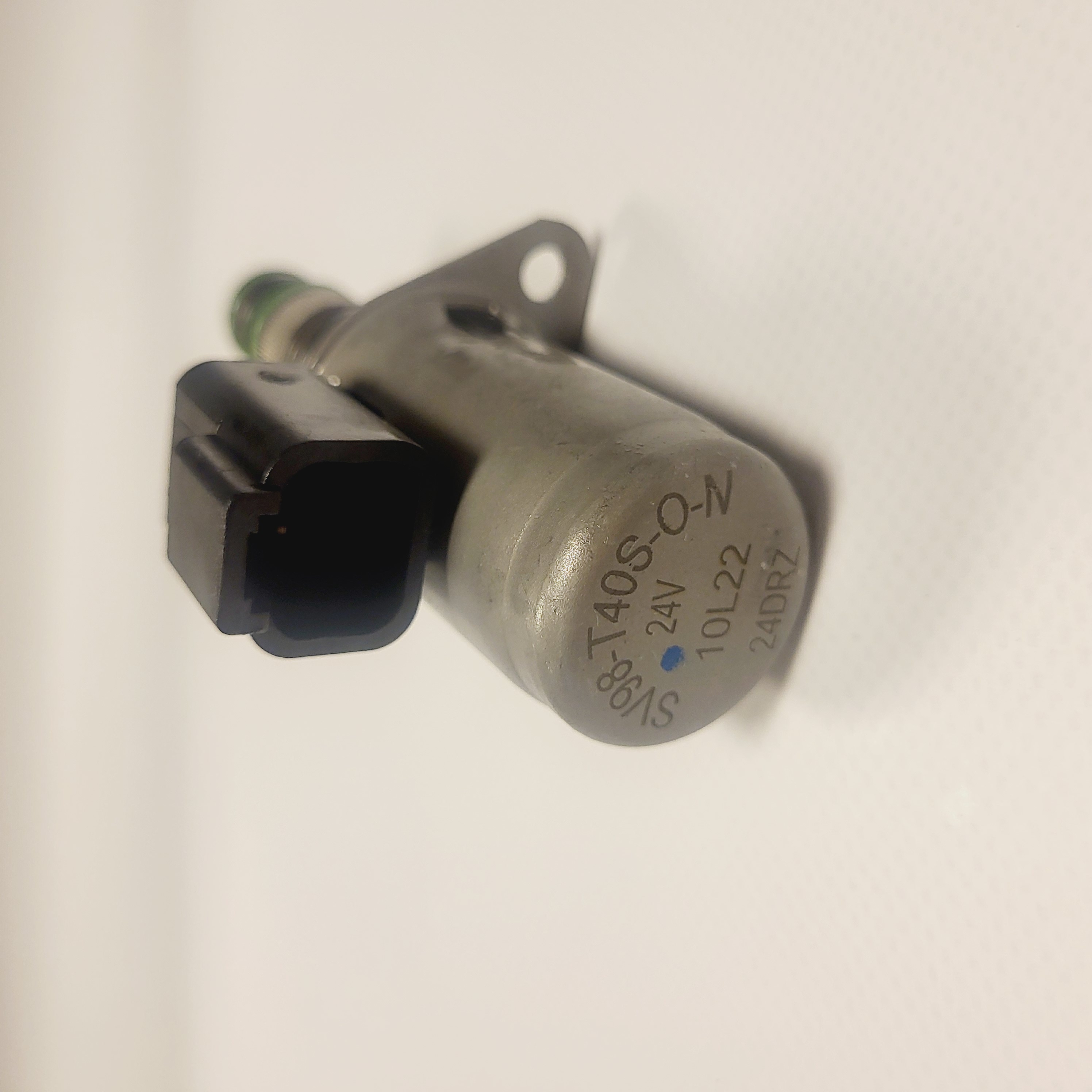
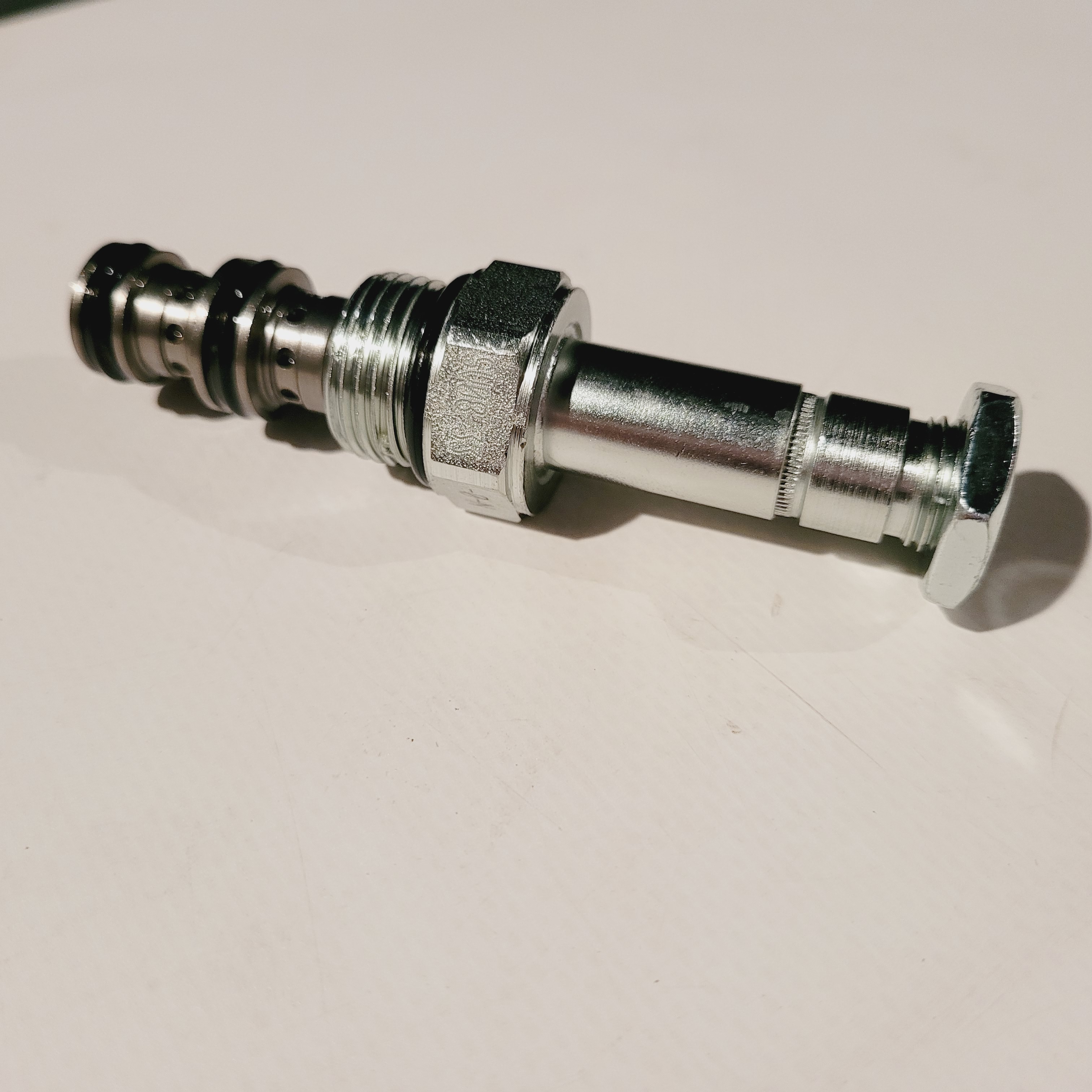
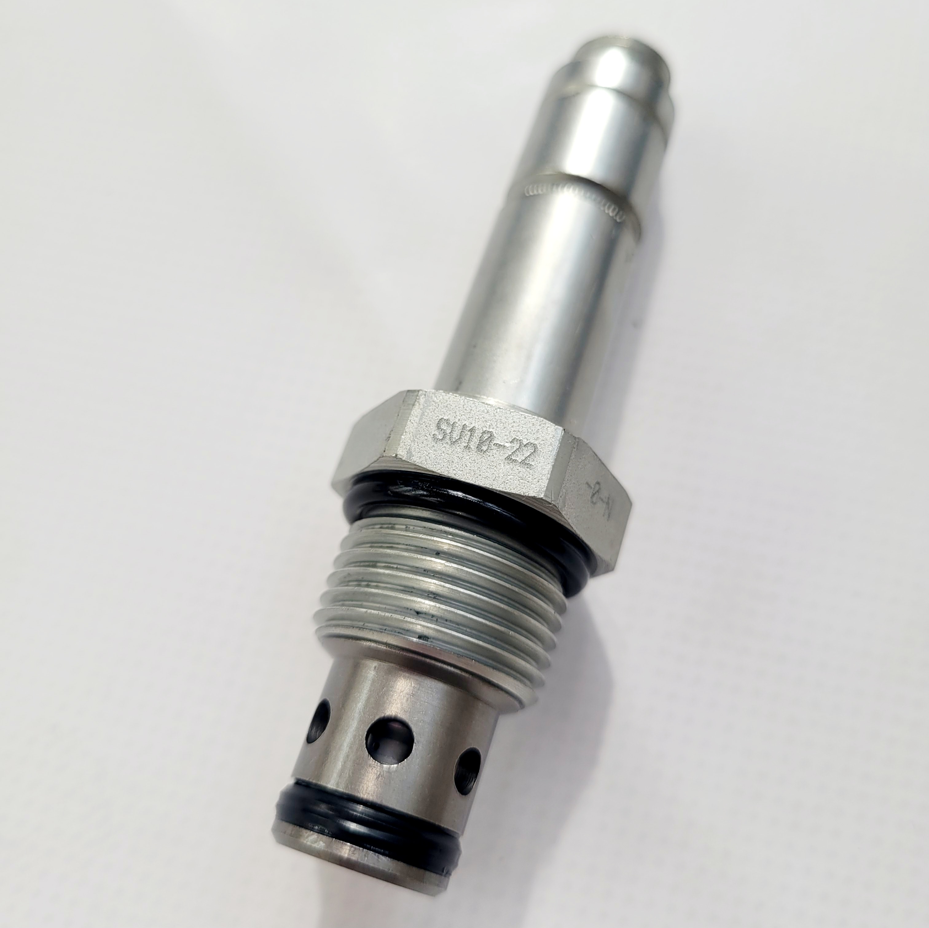
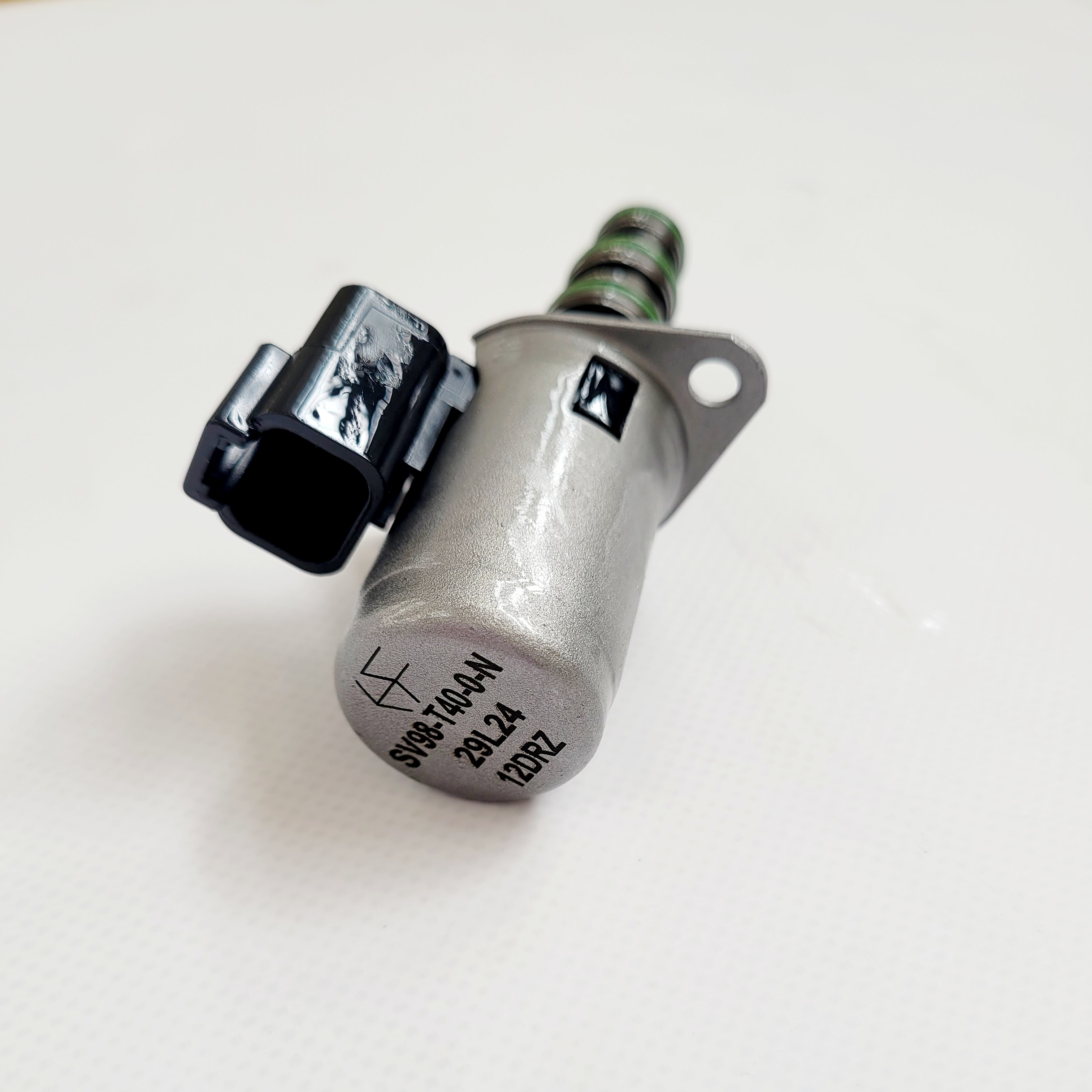
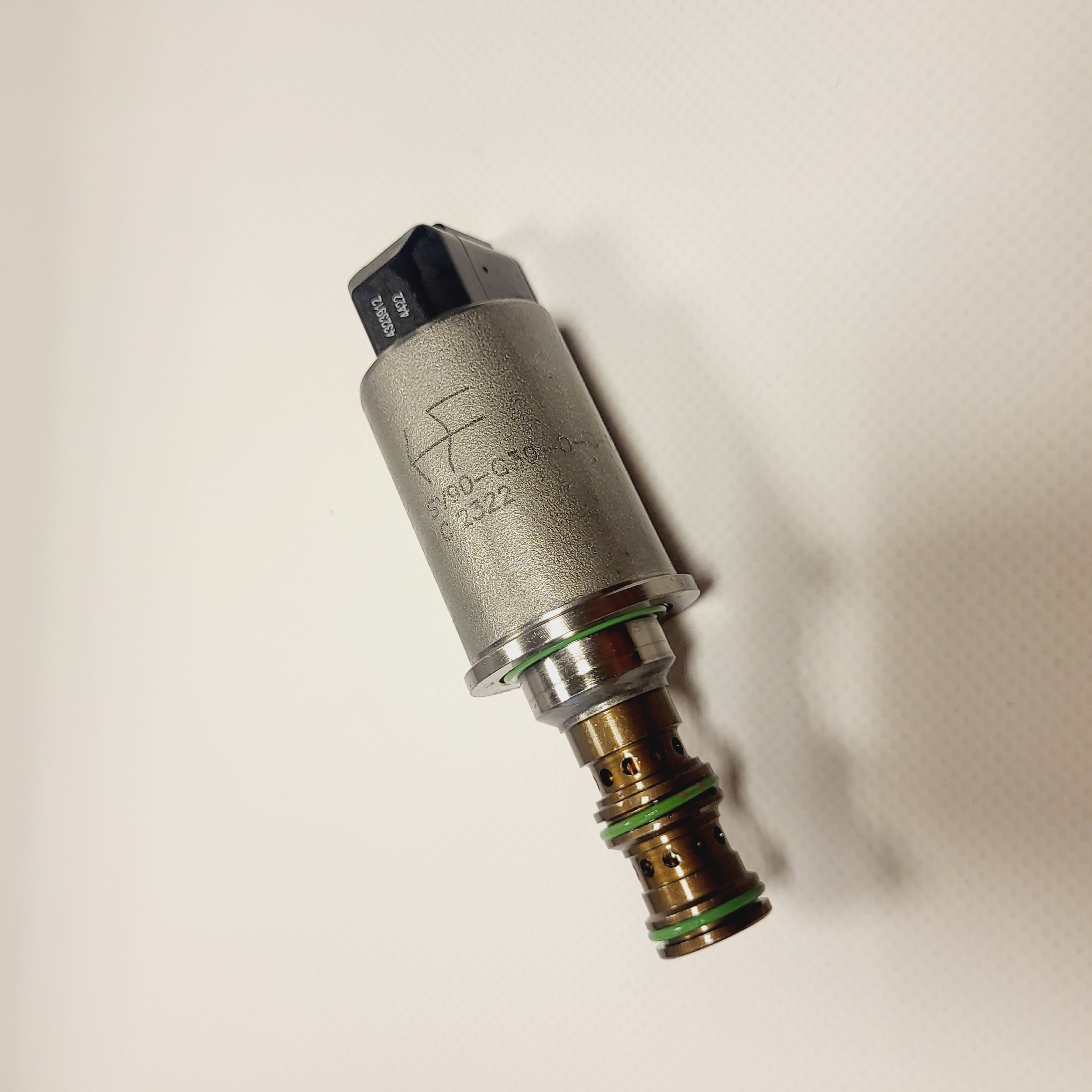
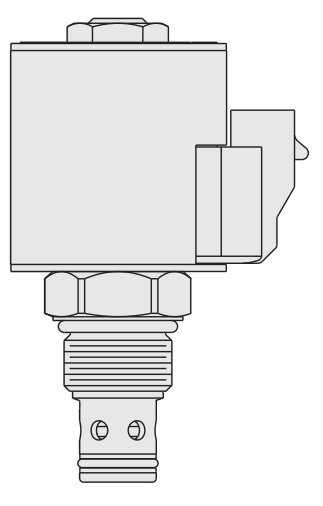
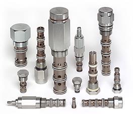
Referenced solenoid cartridge families include HydraForce SV10-20, SV10-21, SV10-22, SV10-28, SV10-29 and SF08-22. Higher-pressure references include HSV10-20, HSV10-21, HSV10-22, HSV10-28 and HSV10-29. Other circuit arrangements include V58-30 and SV10-59D. Check the exact hydraulic function, pressure limit, coil and cavity in the manufacturer's documentation or at www.hydraforce.pl. Multifunction designs such as EP08-35 can combine with other valves in a manifold to reduce the number of separate cavities, subject to the circuit design.
HydraForce proportional valves
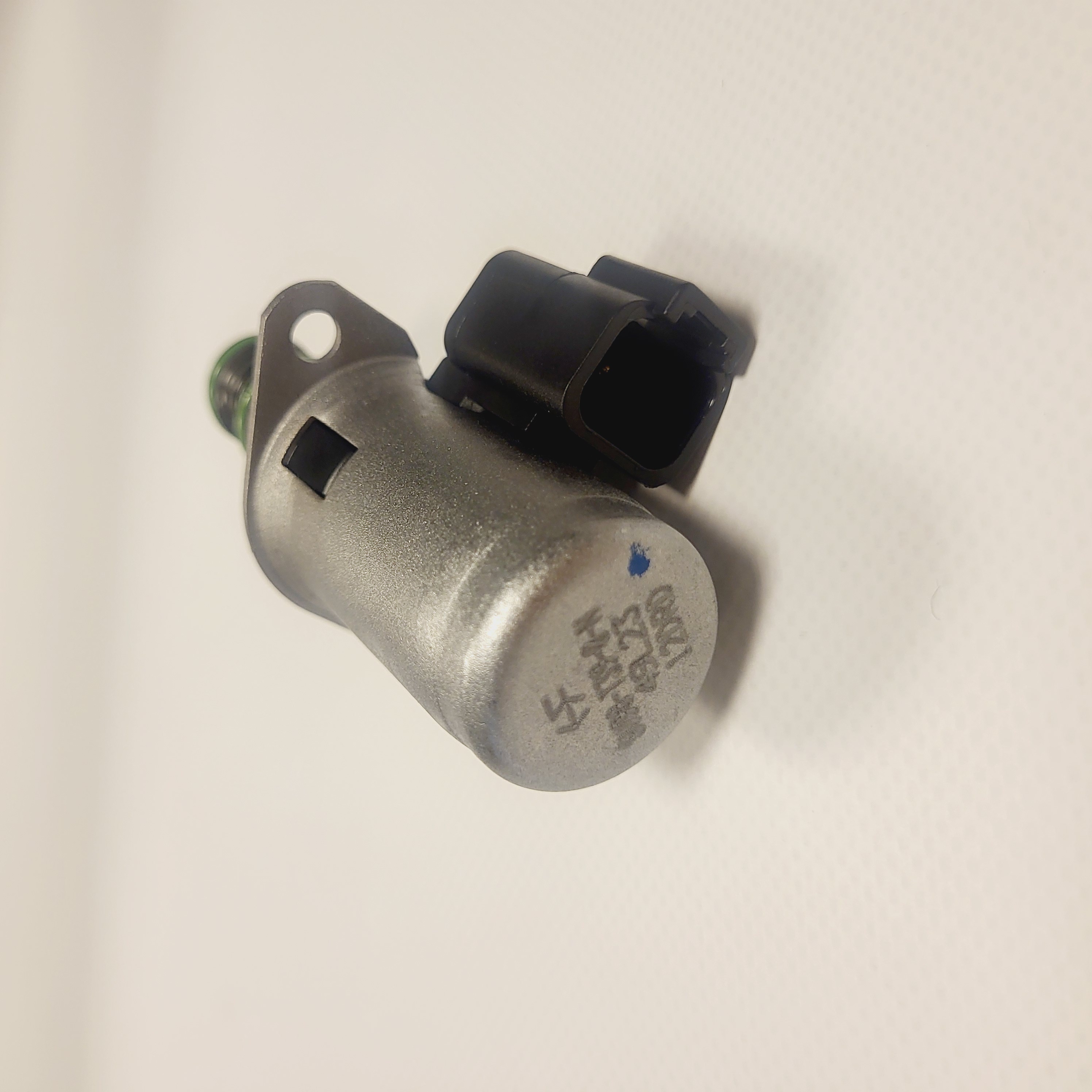
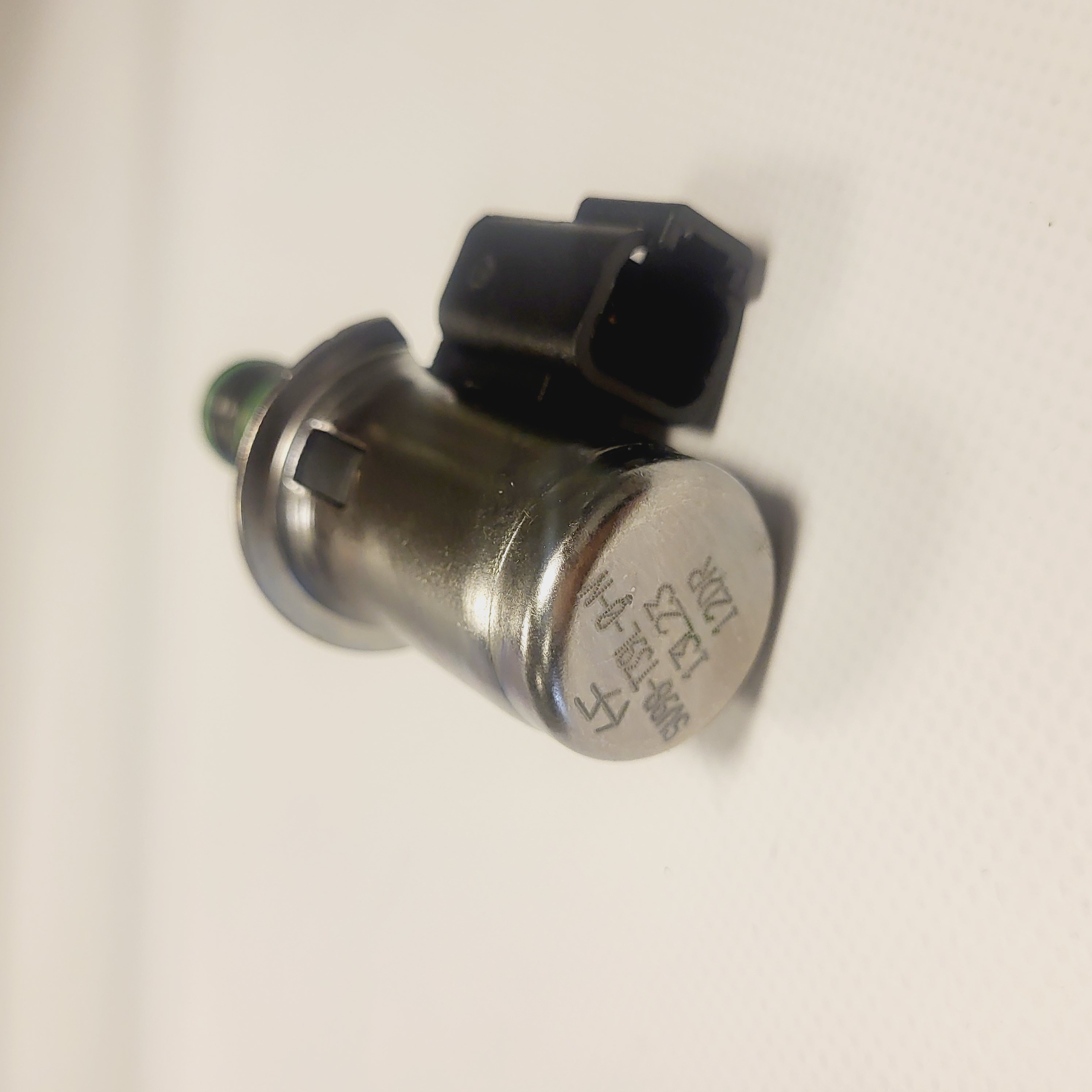
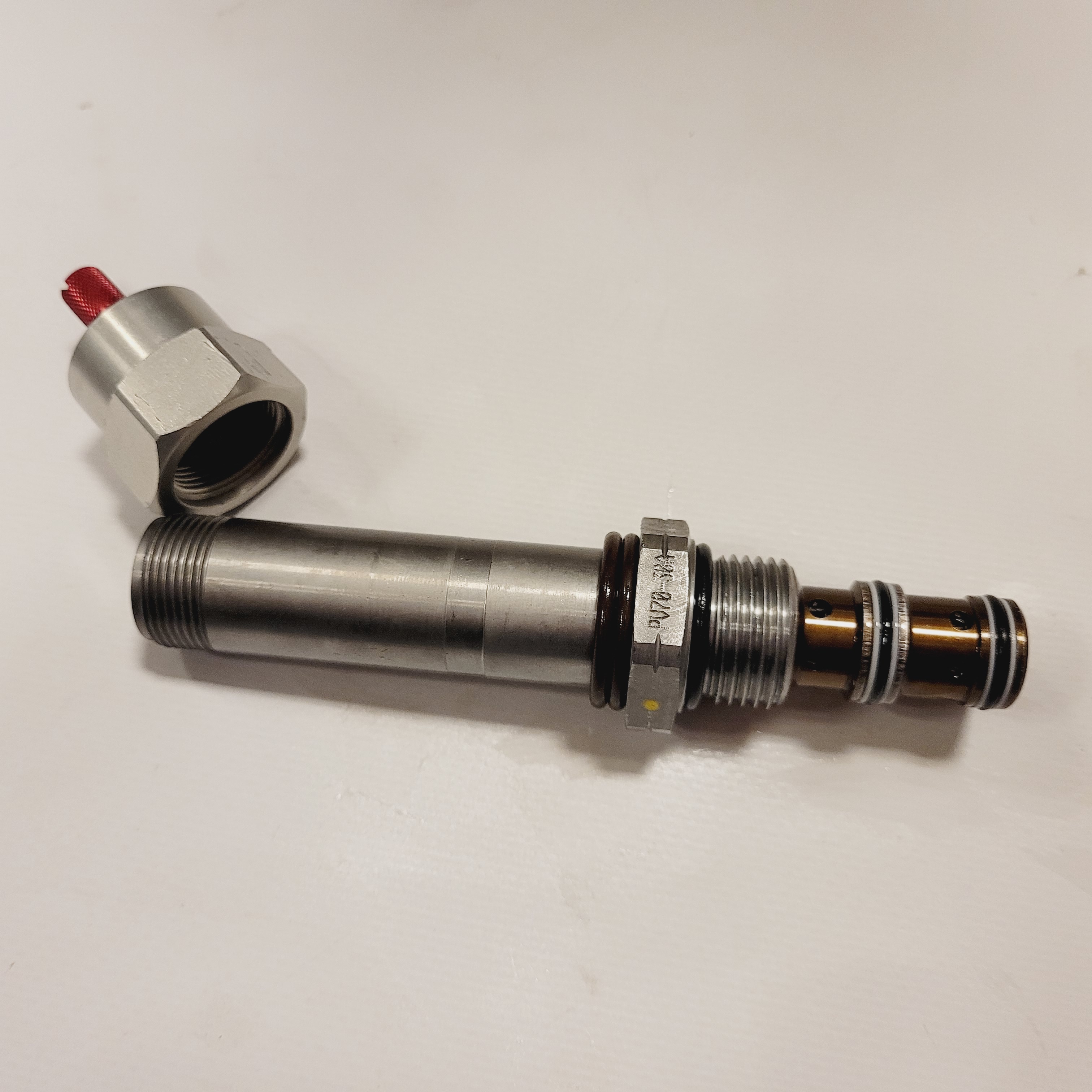
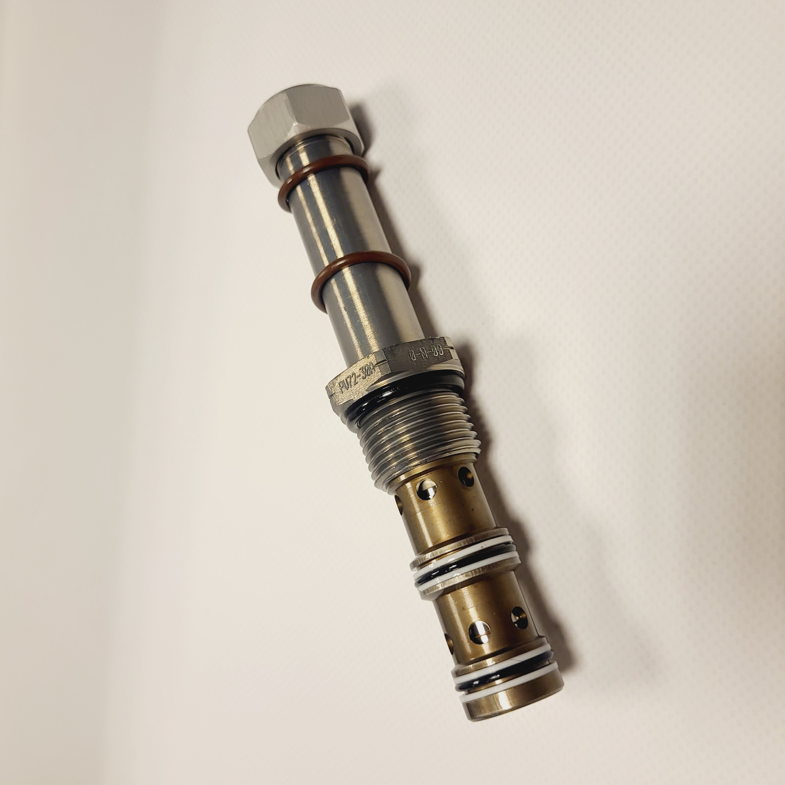
Proportional references include HydraForce PV72-30, SP10-20 and HSP10-20 flow controls, TS10-36 pressure-reducing/relieving valves and TS58-20 relief valves. TS10-27 documentation describes an inverse-acting pressure control used in suitable fan-drive circuits. SP10-57 and SP10-58 references cover proportional directional functions. Listed ordering codes include PV72-30A-0-N-0 and PV72-30AM-0-N-0; verify the current/flow or current/pressure characteristic for the exact version.
HydraForce flow control valves
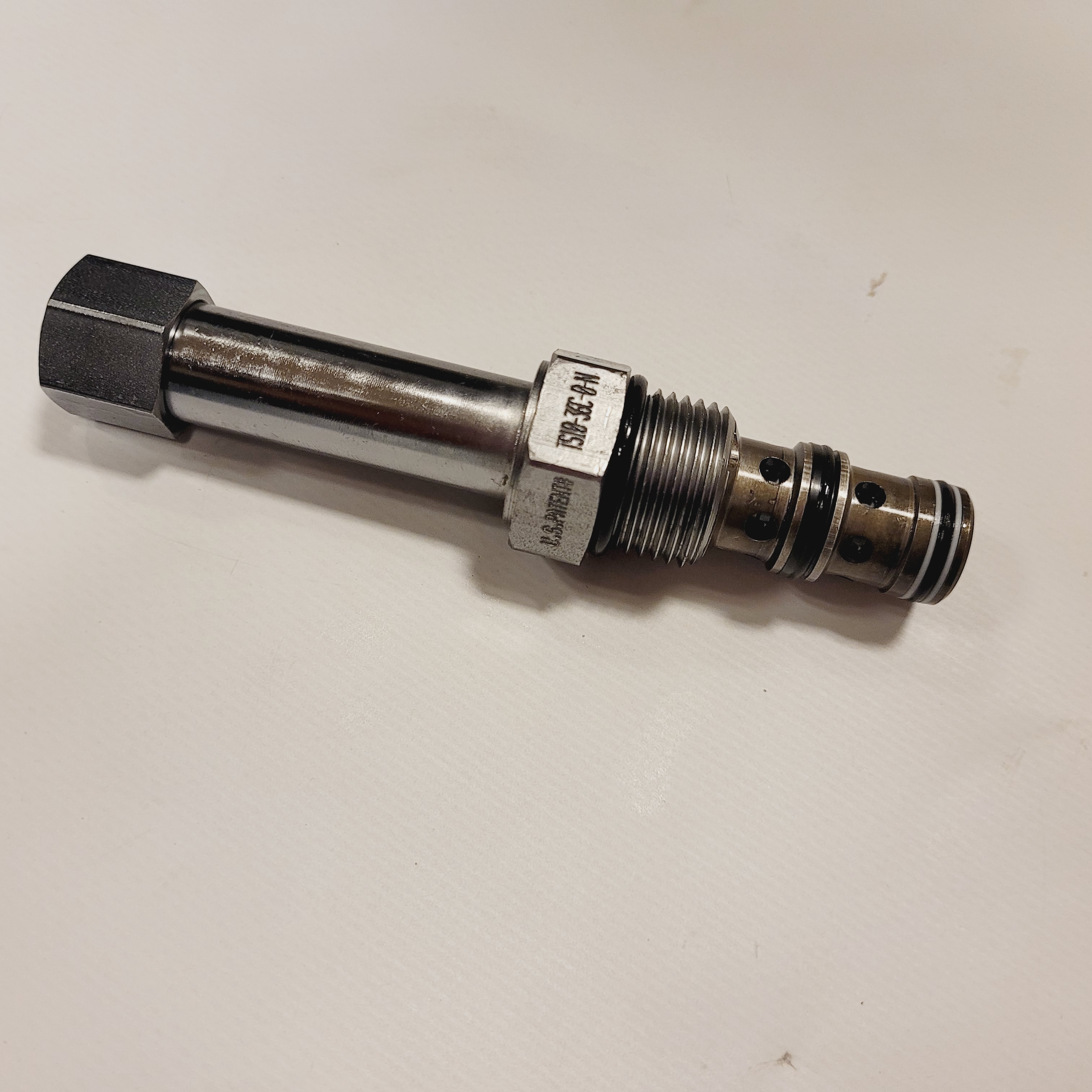
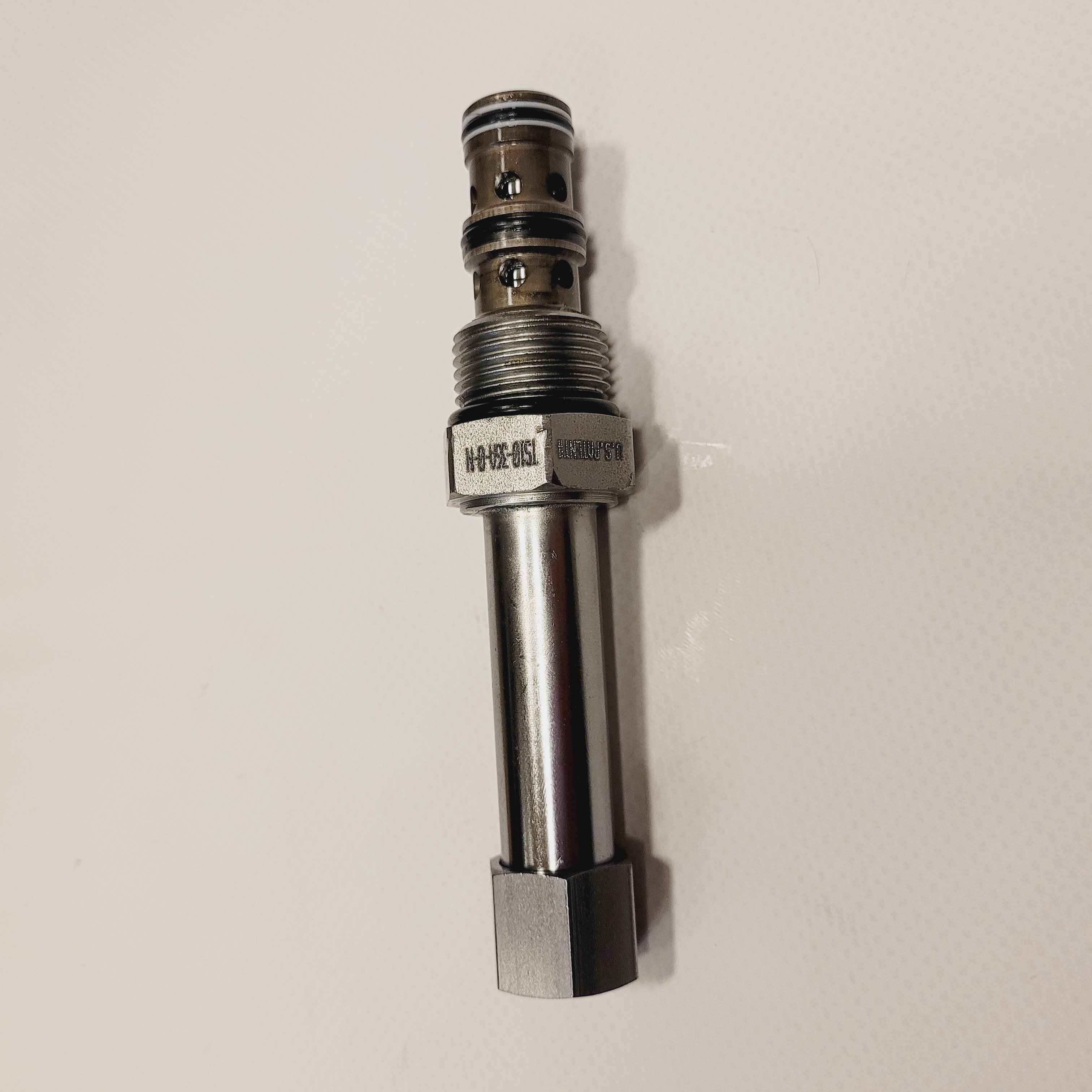
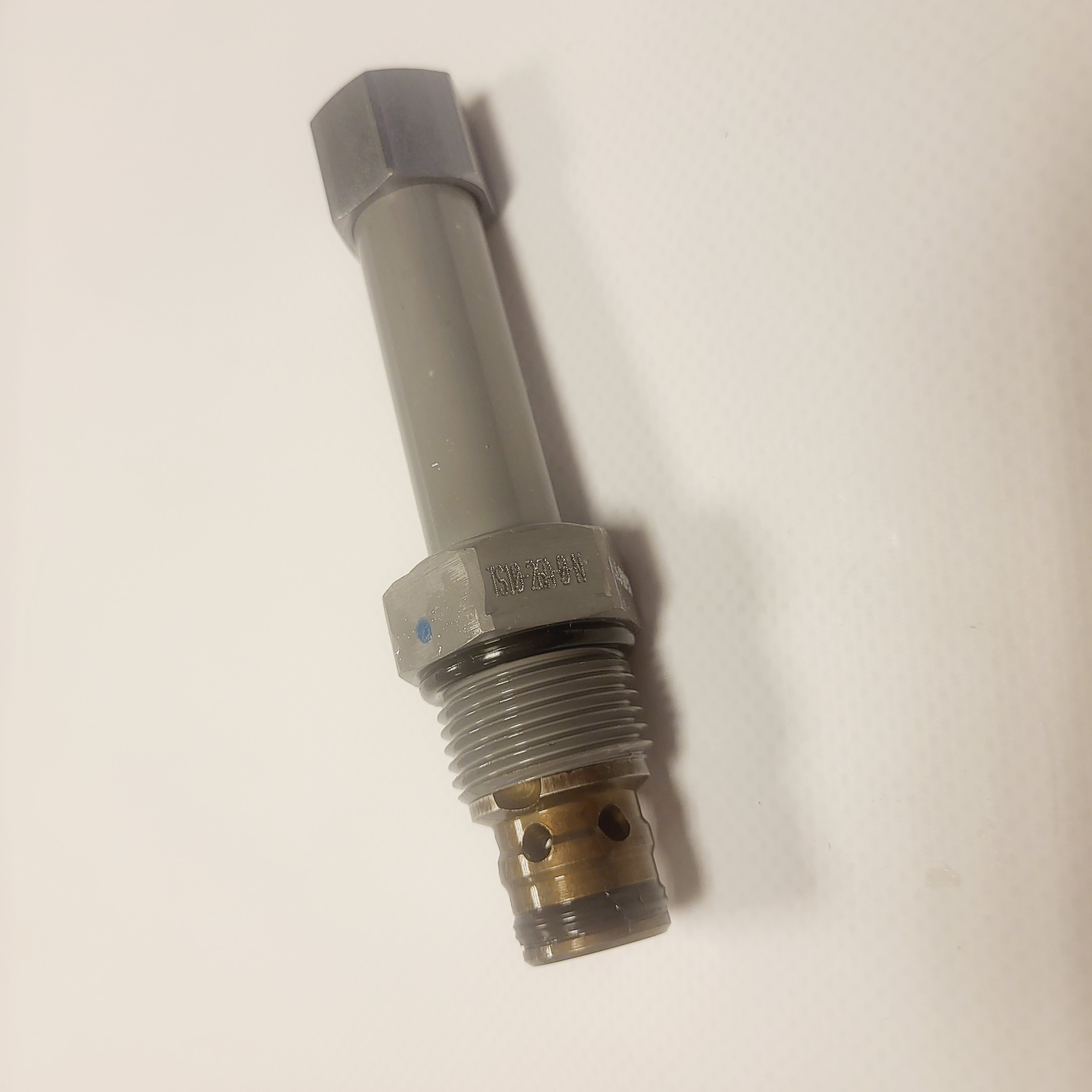
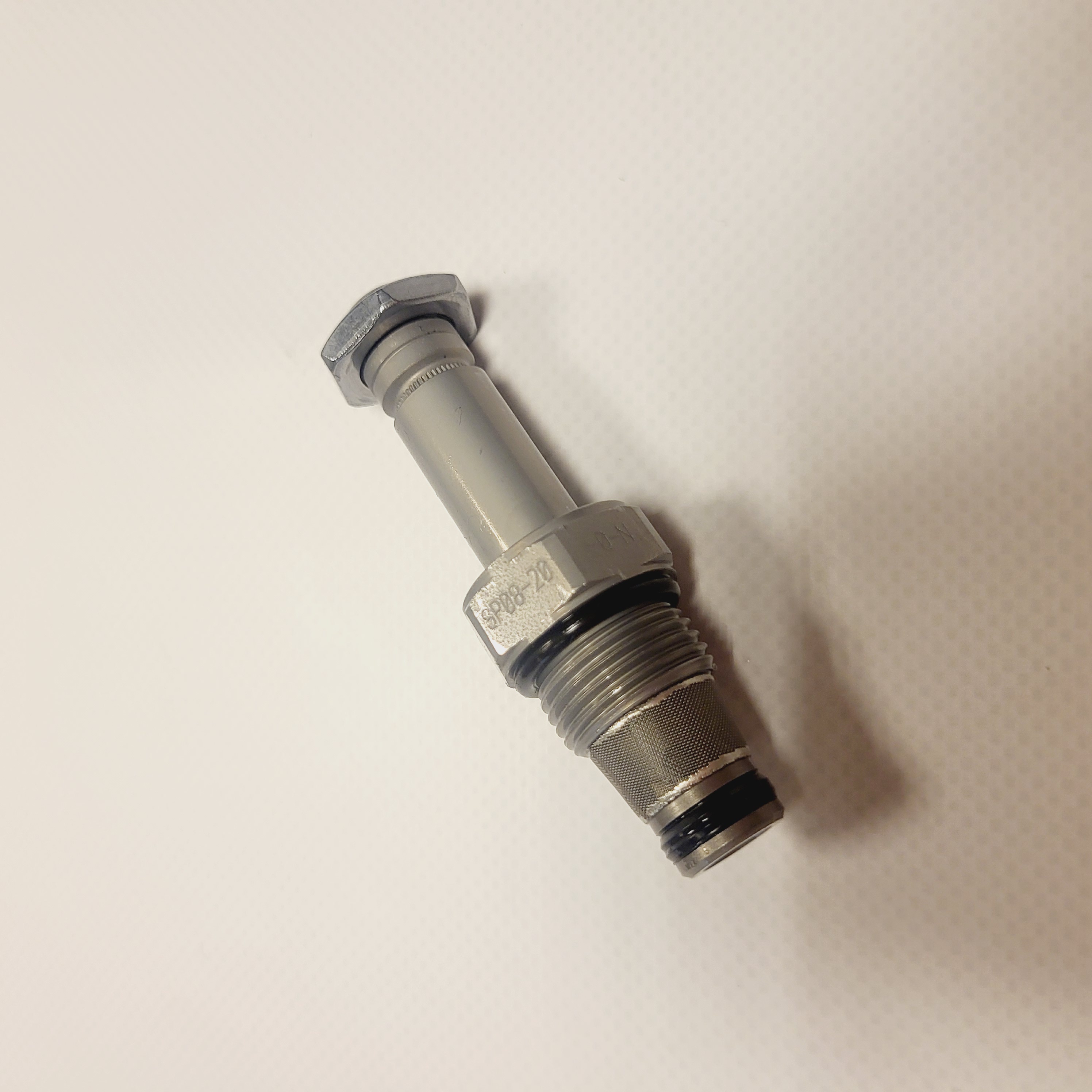
Needle valves such as HydraForce NV10-20 and flow controls with a check function such as FC10-20 meter flow with a pressure-dependent characteristic. Pressure-compensated references include FR50-28 and FR10-39. An EC50-30 compensator may form part of a compensated control arrangement when the circuit is designed accordingly. FD50-45 flow divider documentation describes flow-splitting functions. Check flow range, ratio, accuracy and circuit requirements in each catalogue.
HydraForce pressure control valves
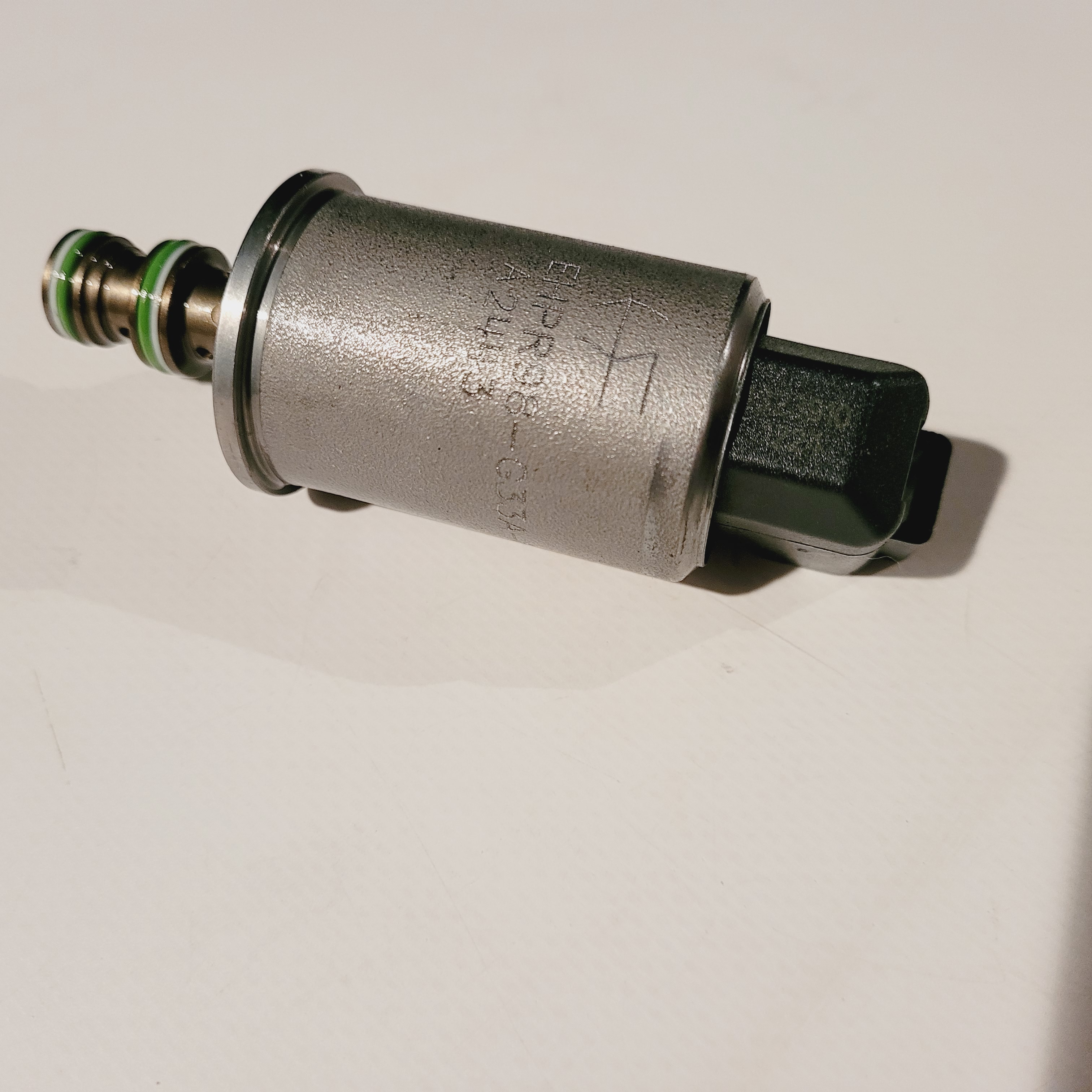
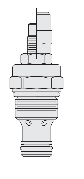
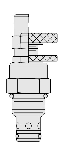
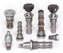
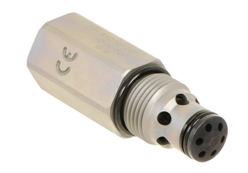
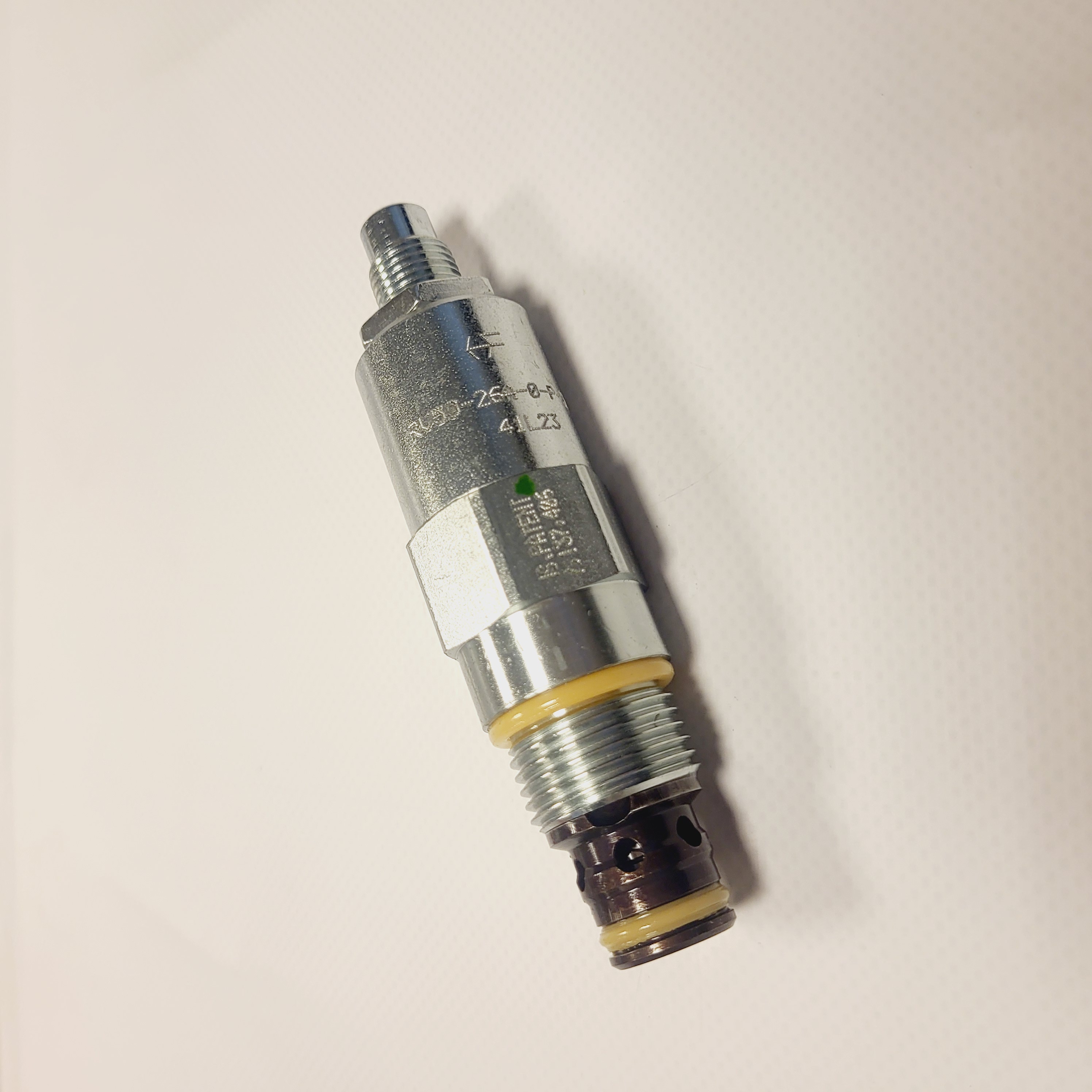
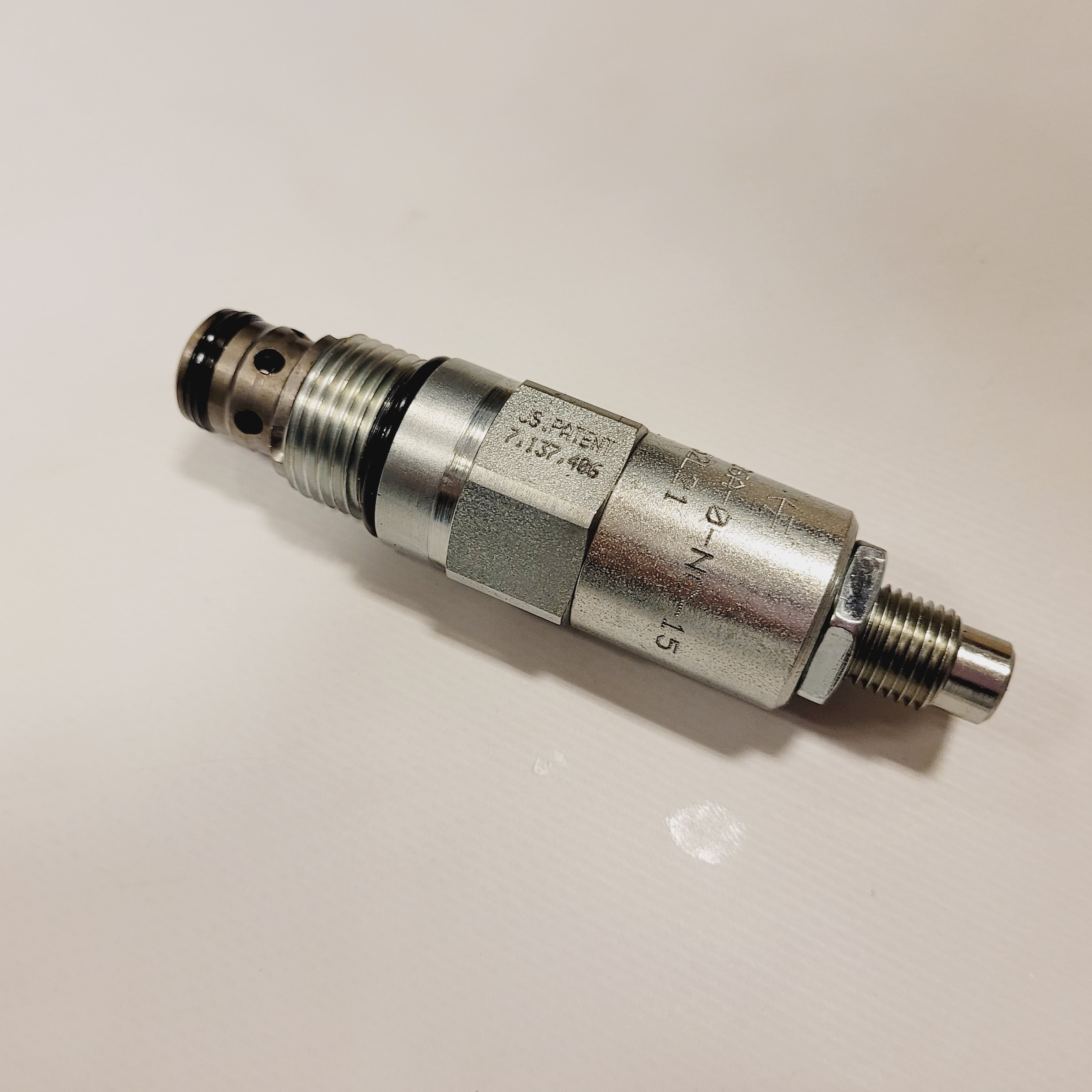
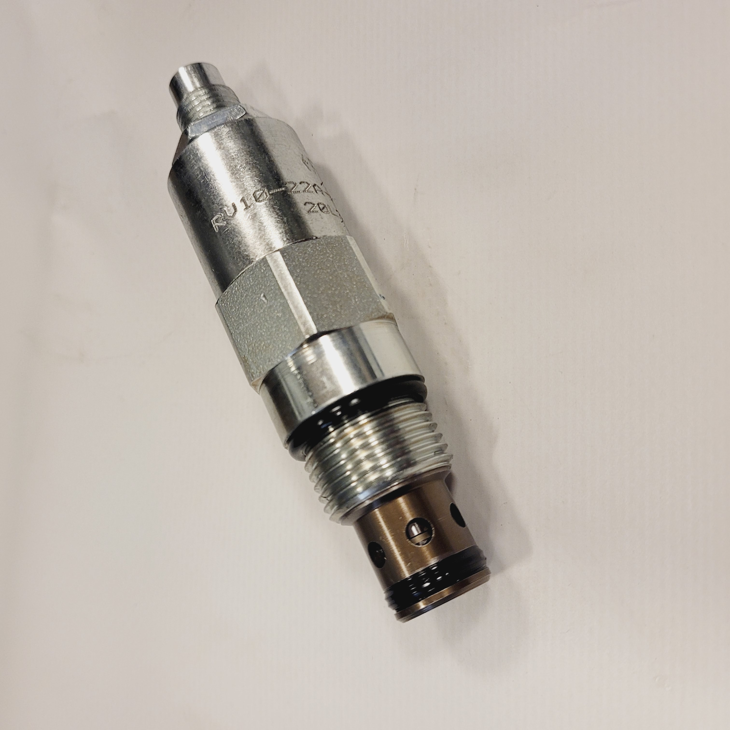
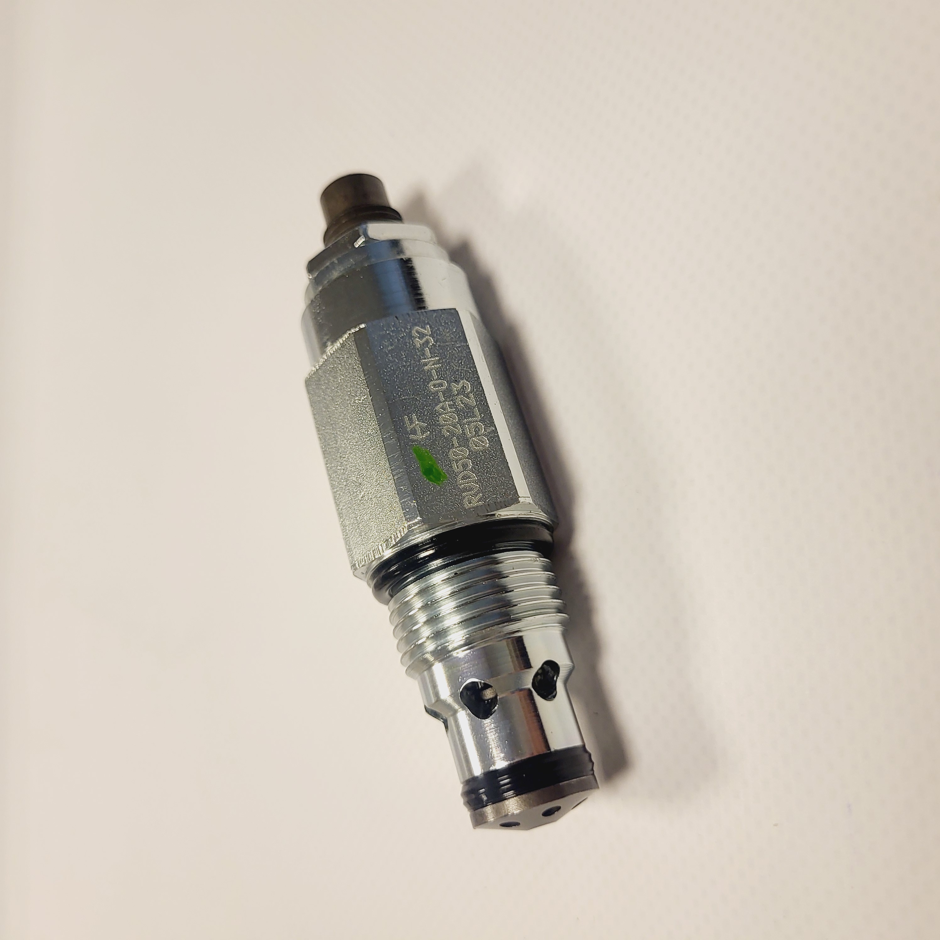
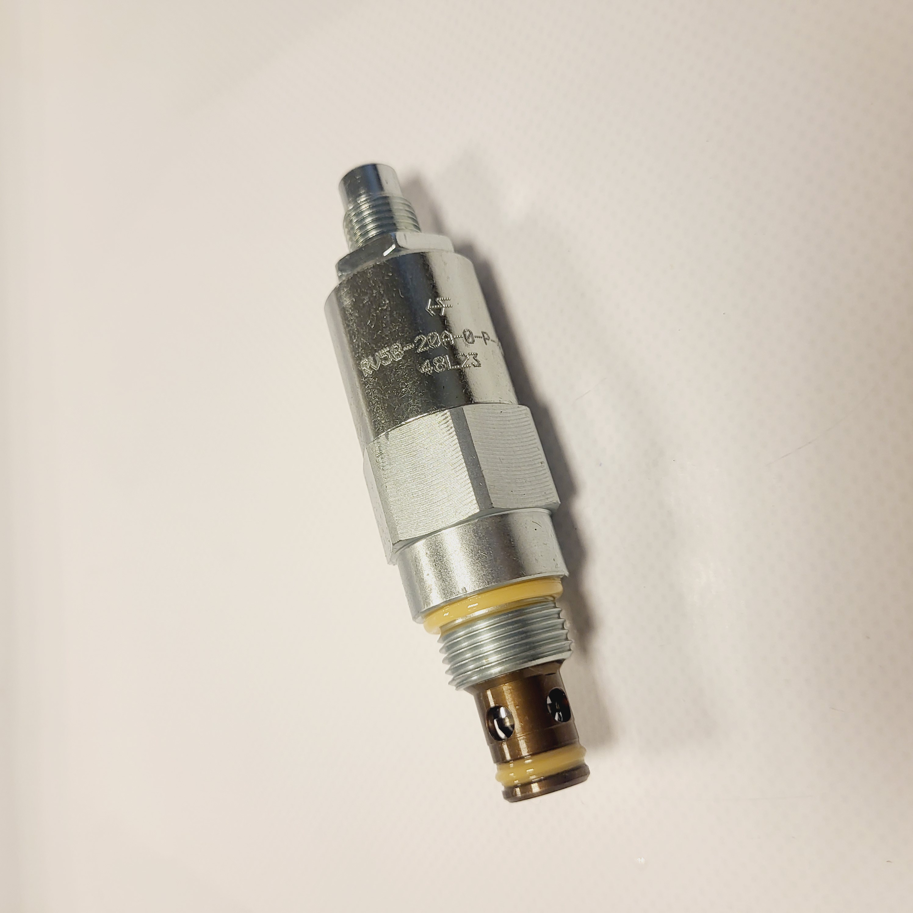
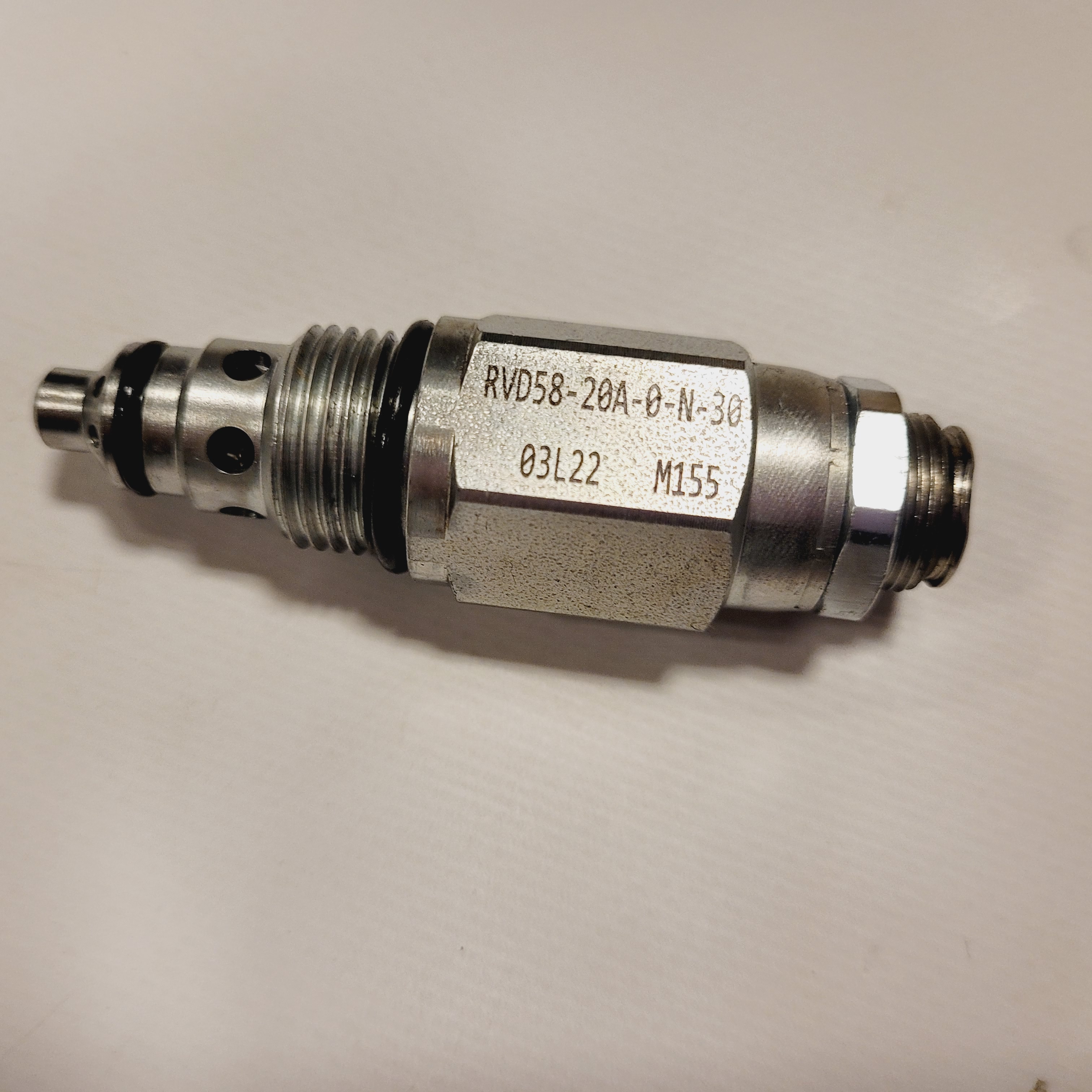
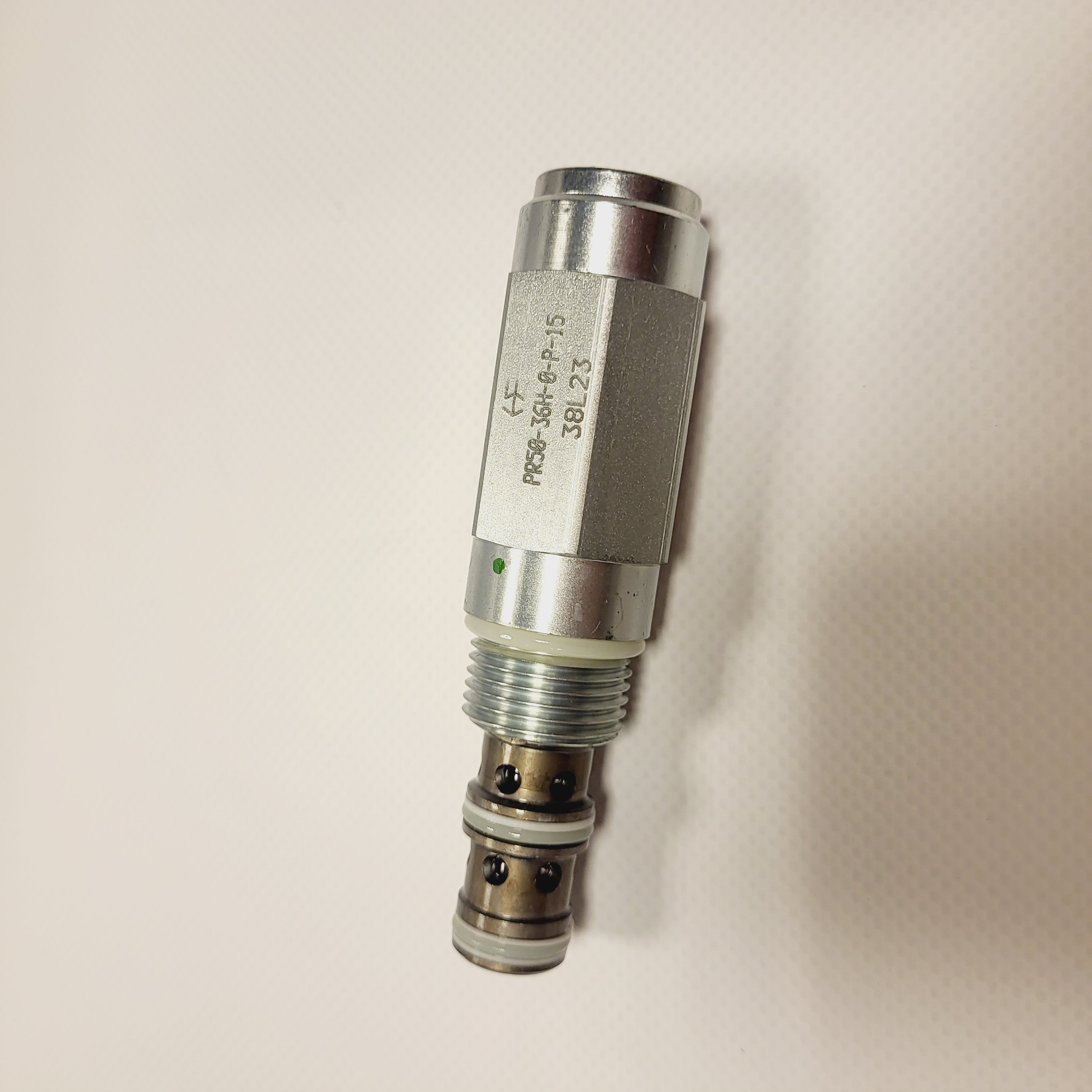
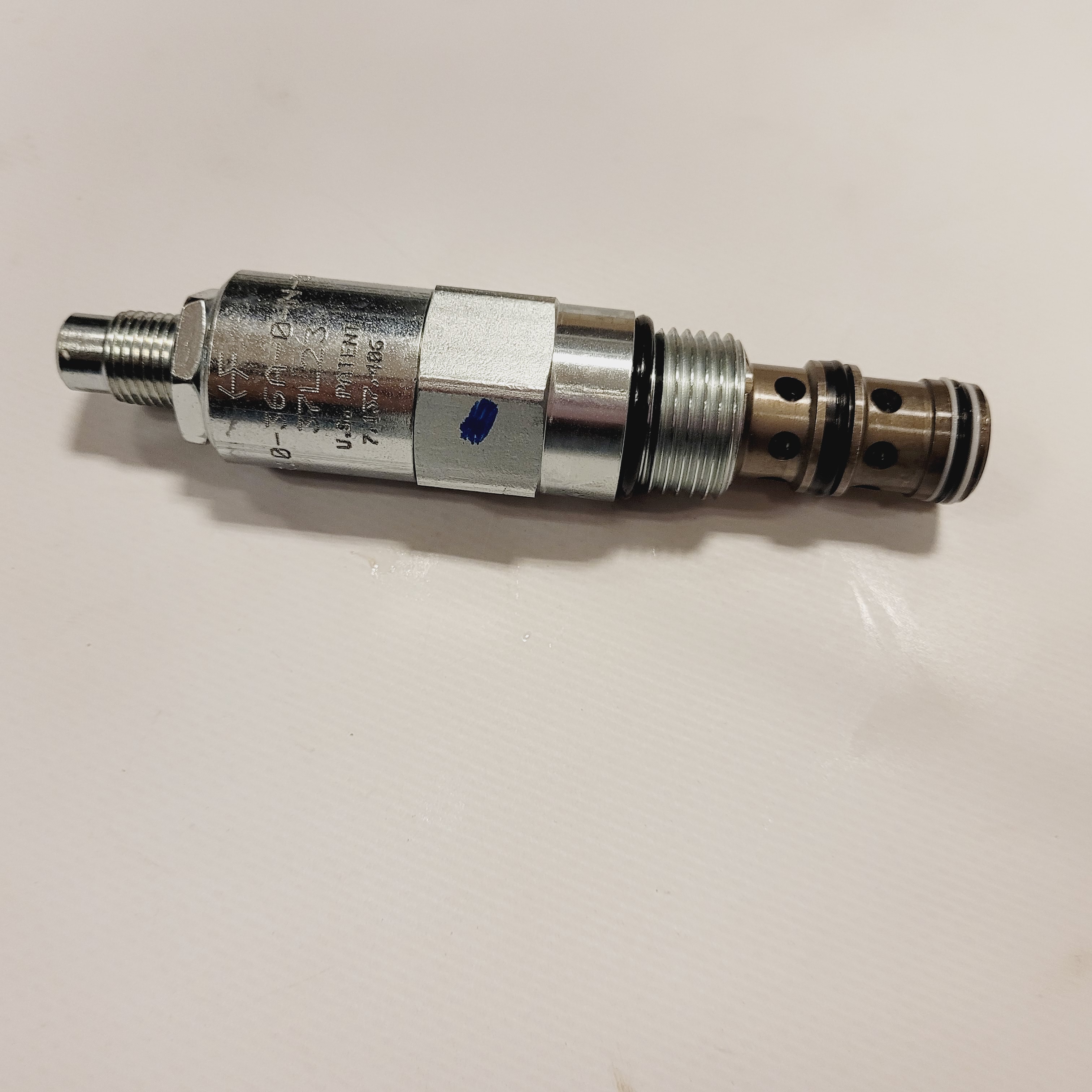
Pressure-control references include HydraForce RVD50-20, RV10 and RV50 relief valve families, PR50-36 pressure-reducing/relieving valves, and PS10-30 and PS10-40 sequence valves. Select the operating range, flow capacity and dynamic response for the circuit; check the manufacturer's performance curves and settings.
HydraForce directional control valves
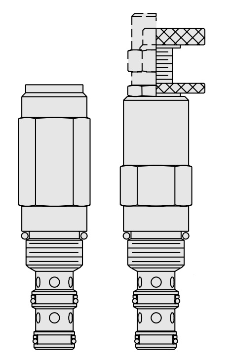
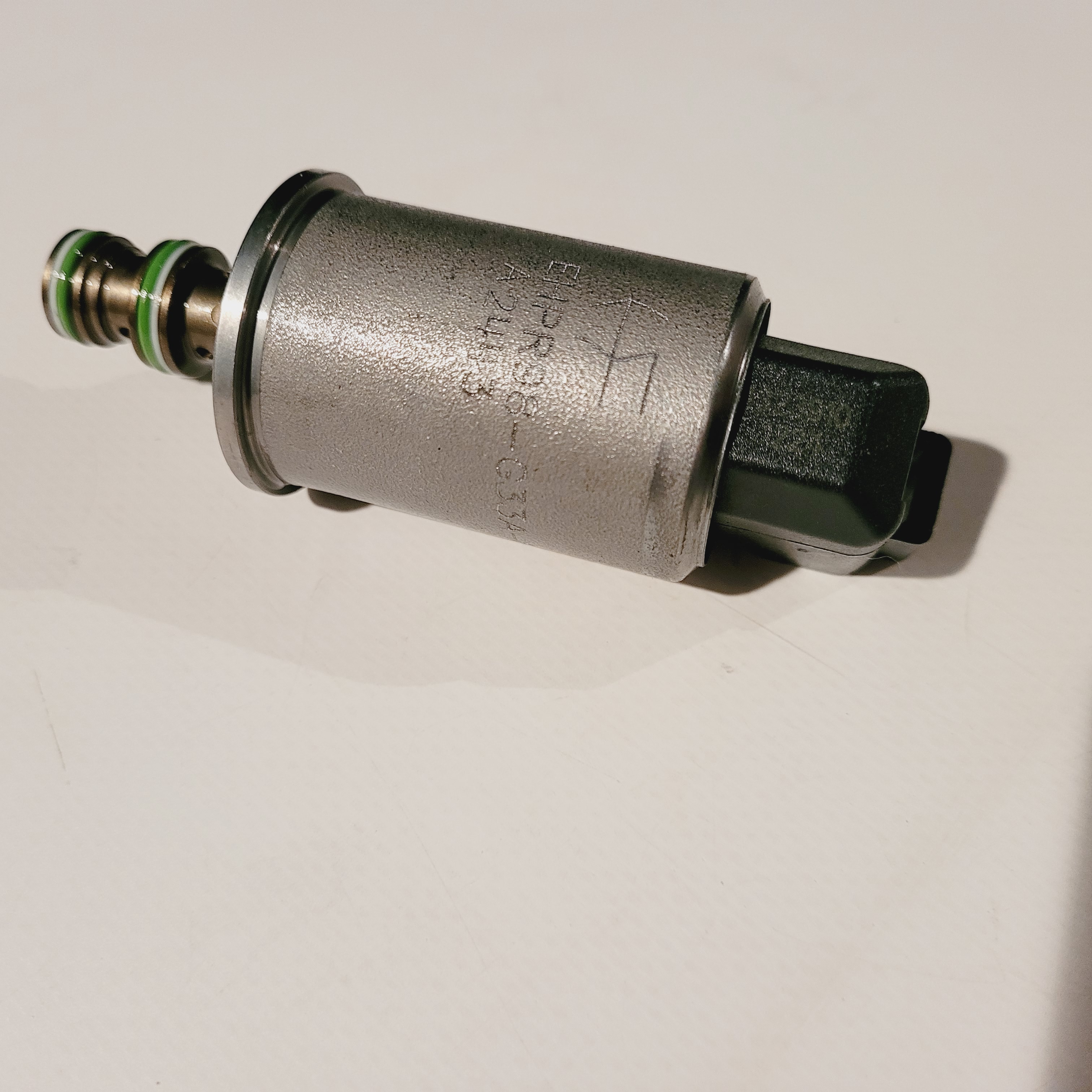
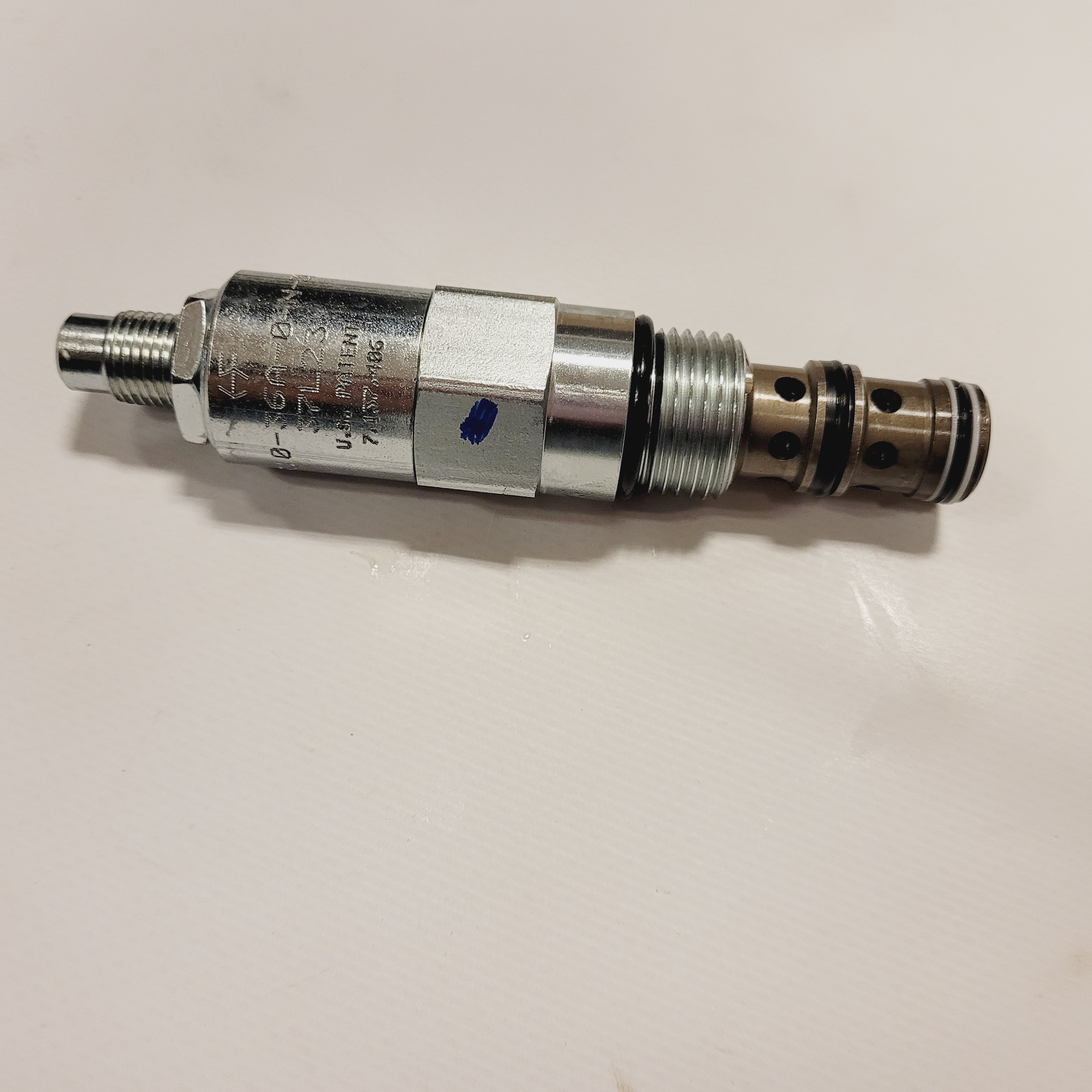
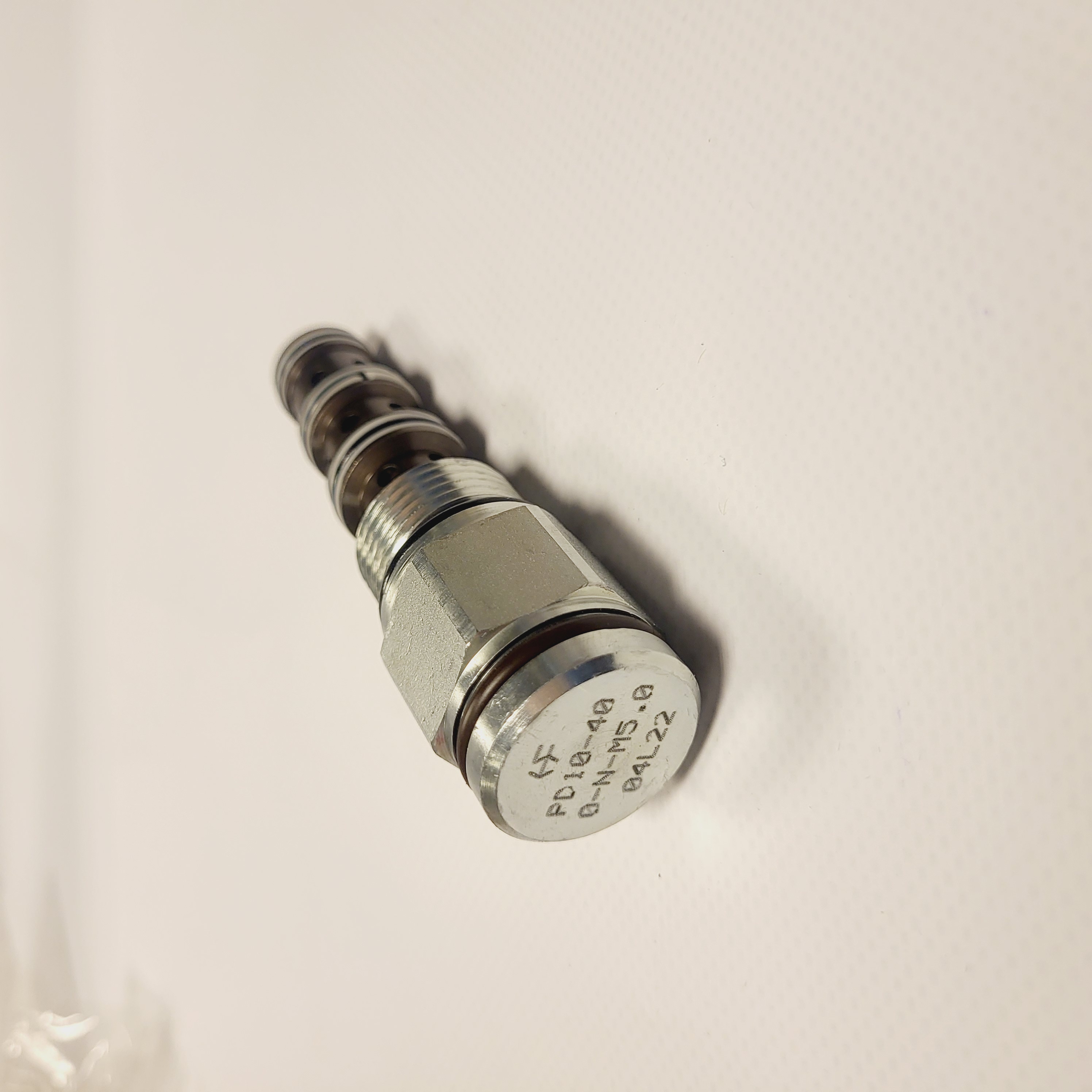
Directional and logic references include HydraForce EP10-S38 and pilot-operated PD10-30, PD10-40 and HPD42-S67C designs. Associated circuit components include LS10-30 and LS50-30 shuttle valves and CV10-30 and HCV10-30 check valves. The pilot arrangement and hydraulic symbol determine the function; compare these with pressure drop, flow and installation requirements.
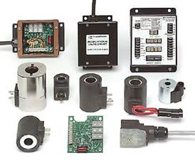
Coils, spool position sensors and multifunction valves
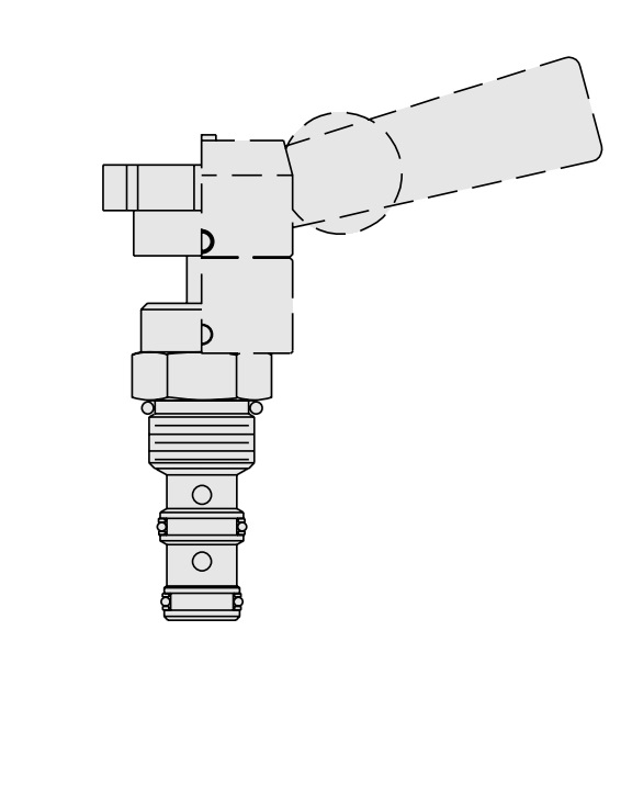
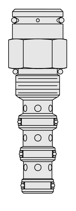
Multifunction cartridge designs combine hydraulic functions within a single component and can help simplify a manifold. Referenced HydraForce designs include SVRV10-26, PC10-38, RVCV56-20, HSPEC12-30A, HSPEC12-34 and EPFR50-S35. Verify the complete function and operating limits in the individual data sheet.
Traction, transmission and accumulator applications
Application-specific references include HydraForce HTD10-40 torque dividers, HCV16-30 check valves and transmission valve arrangements. Contact us with the machine requirements and circuit diagram to discuss component or manifold selection.
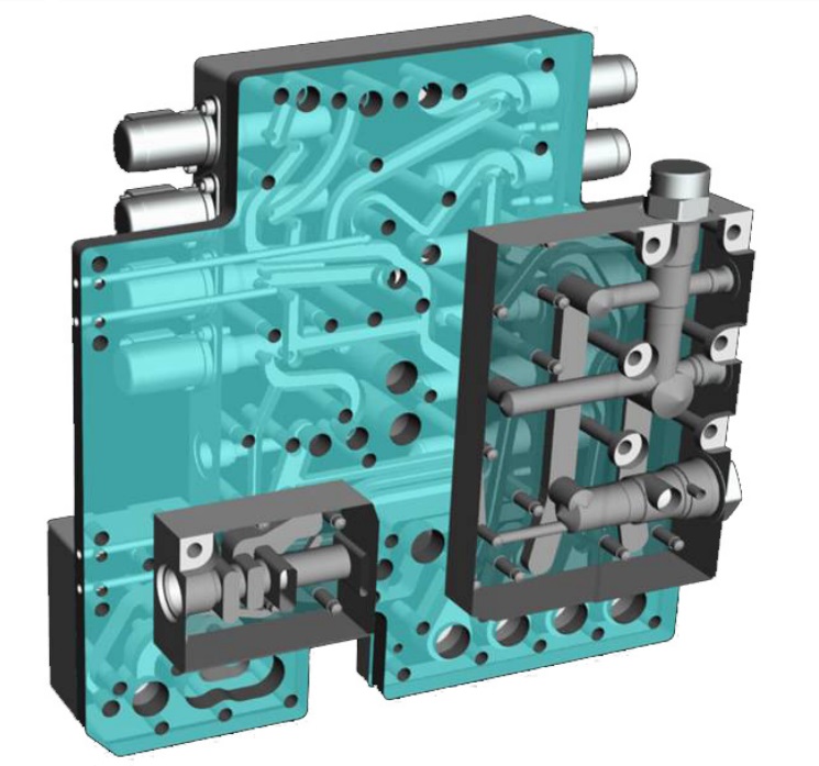
HydraForce transmission valves for integrated installation
Machine-specific valve and manifold arrangements require coordinated hydraulic and mechanical design. Use the transmission documentation as a starting point, then confirm the installation details and control requirements for the application.
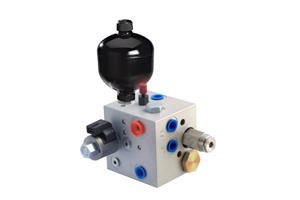
HydraForce solutions for accumulator circuits
Accumulator circuits can supply oil during periods of peak demand. The linked HydraForce brochure introduces associated valve and manifold arrangements. Selection must consider charging, isolation, discharge and the requirements of the complete accumulator installation.

HydraForce housings
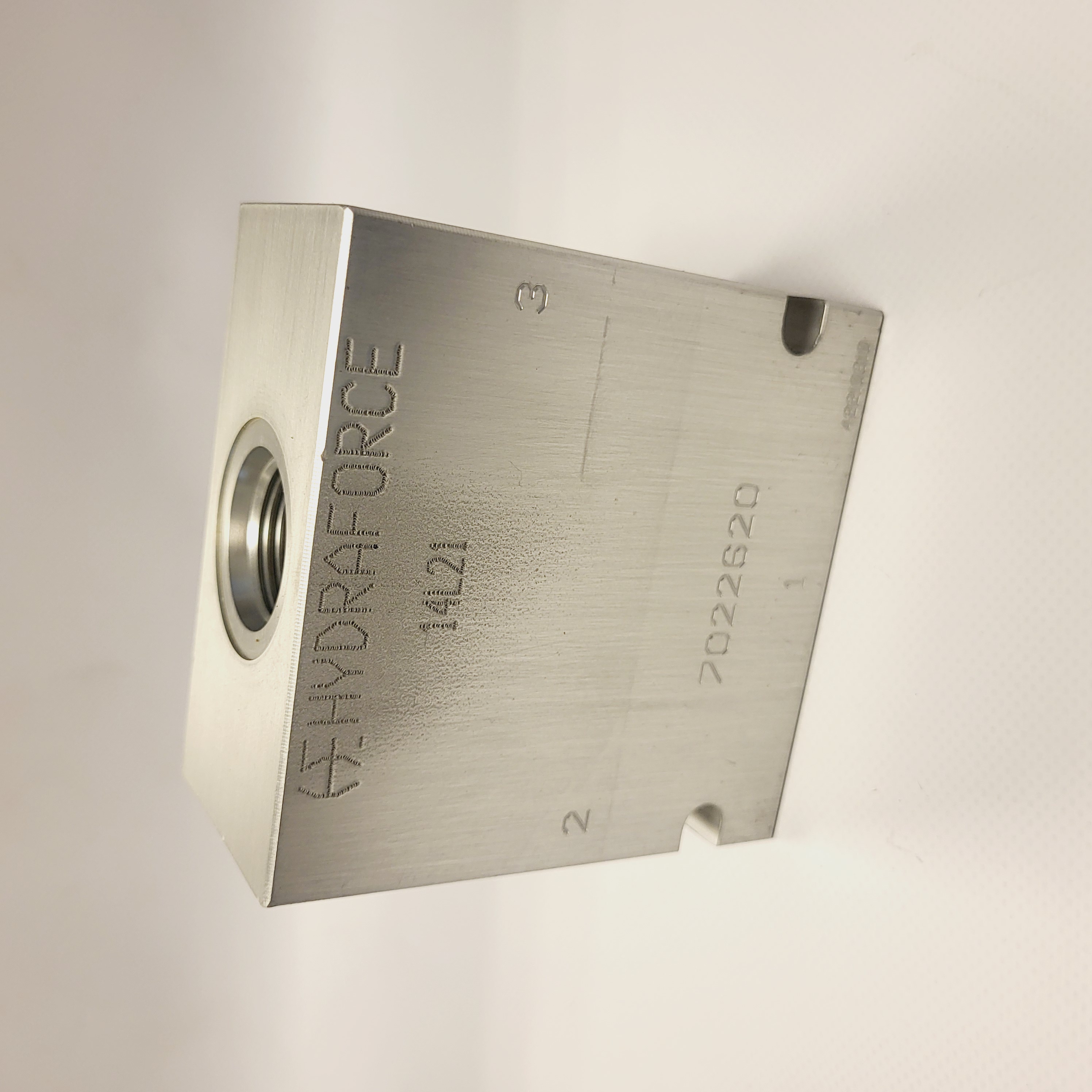
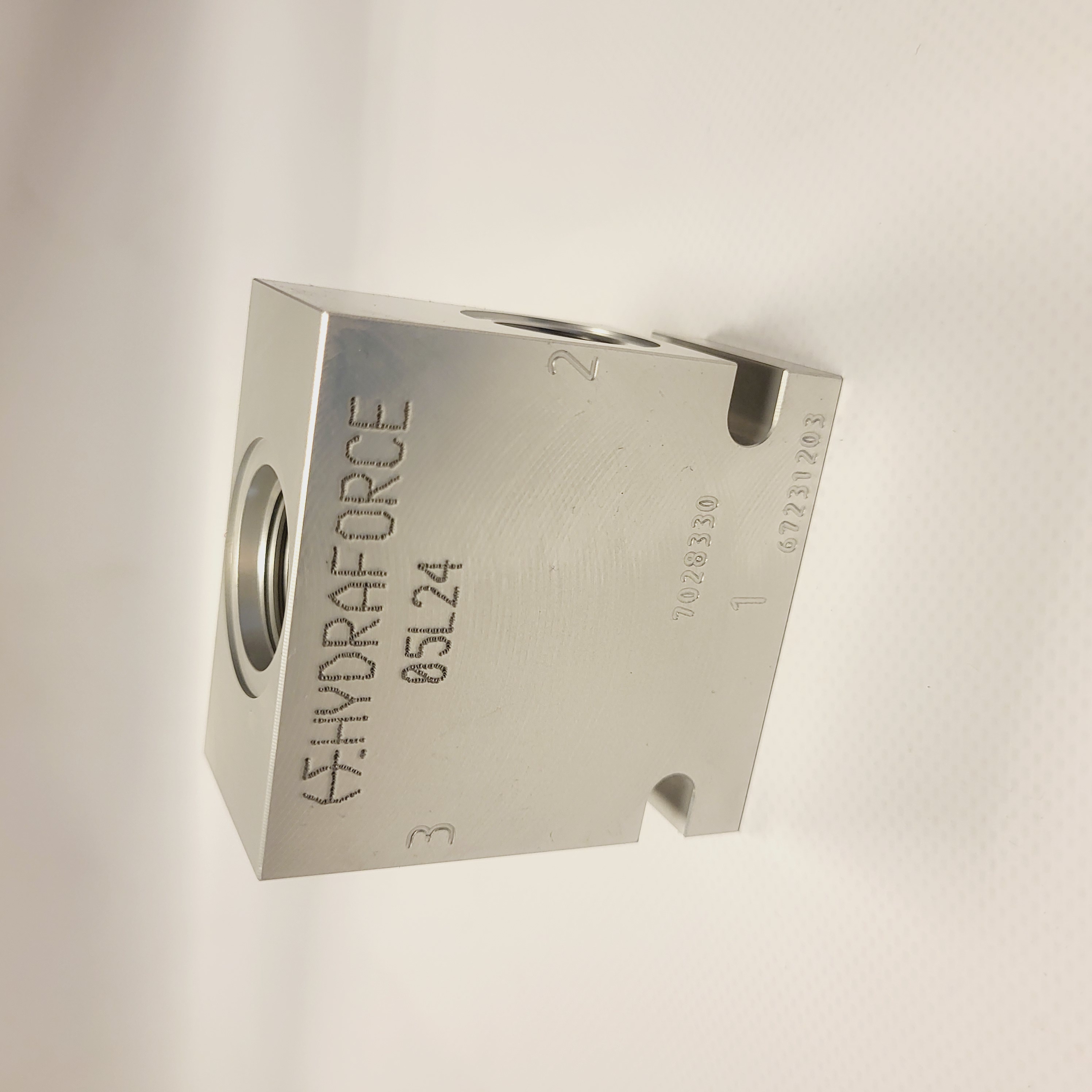
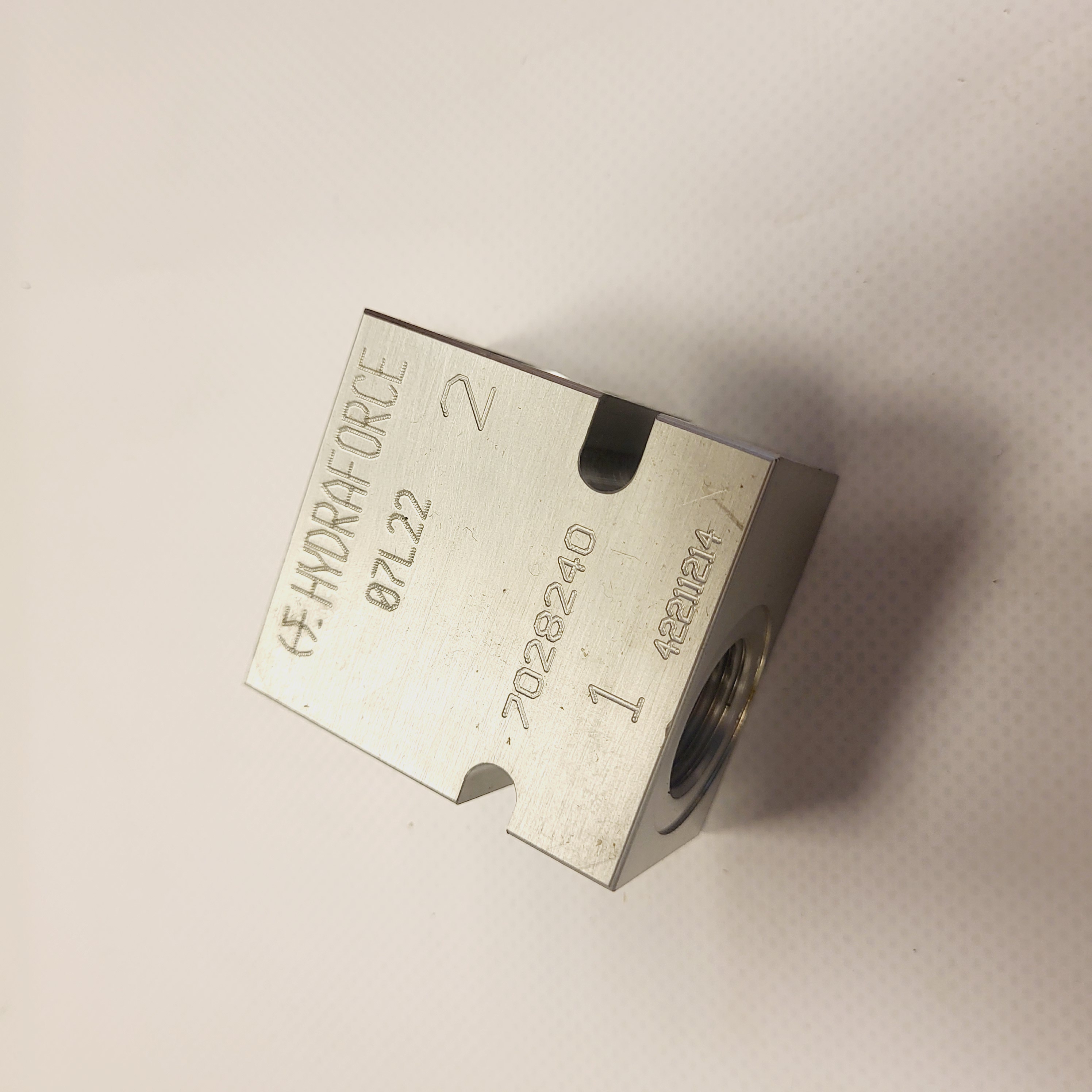
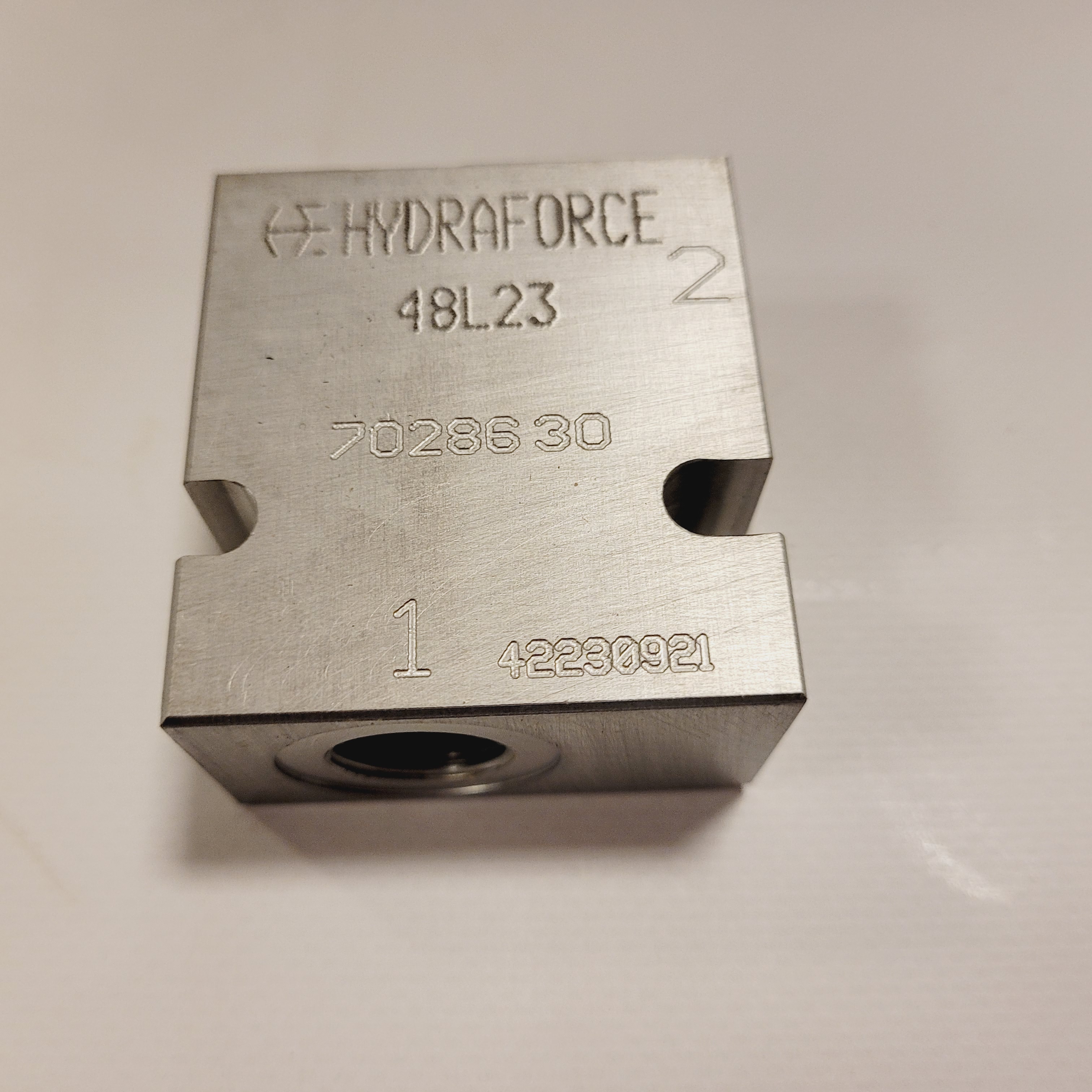
Alongside custom manifolds, the documentation includes standard HydraForce housings. Referenced numbers include 7028240, 7028330, 7151450, 7151540, 7151050 and 7151150. Compare cavity, port threads, material and pressure rating, or contact us about a custom arrangement.

Danfoss — legacy Eaton / Integrated Hydraulics documentation
This section groups legacy Eaton and Integrated Hydraulics cartridge documentation to support identification of components in service. References include 1CE, CEB, CER and CEL counterbalance families and the 39055-FAZ self-levelling manifold. Compare the full model code and circuit function before requesting a replacement or a new manifold assembly.
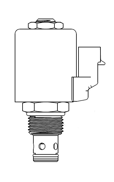
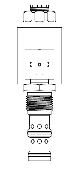
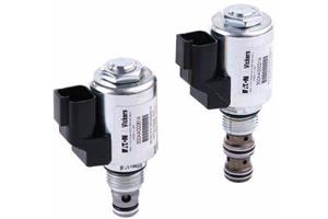
Eaton proportional cartridge references include 2-way ESV1-10 and 3-way EFV2-12 flow controls, ERV1 relief valves, IRV1 and IRV2 inverse-acting controls for suitable fan-drive circuits, and EPRV pressure-reducing/relieving valves. Contact us to discuss a manifold combining several functions.
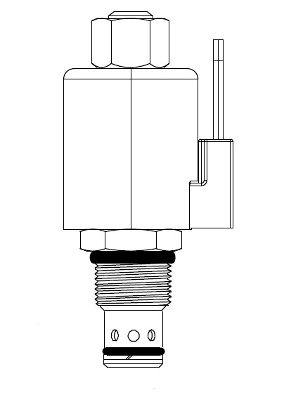
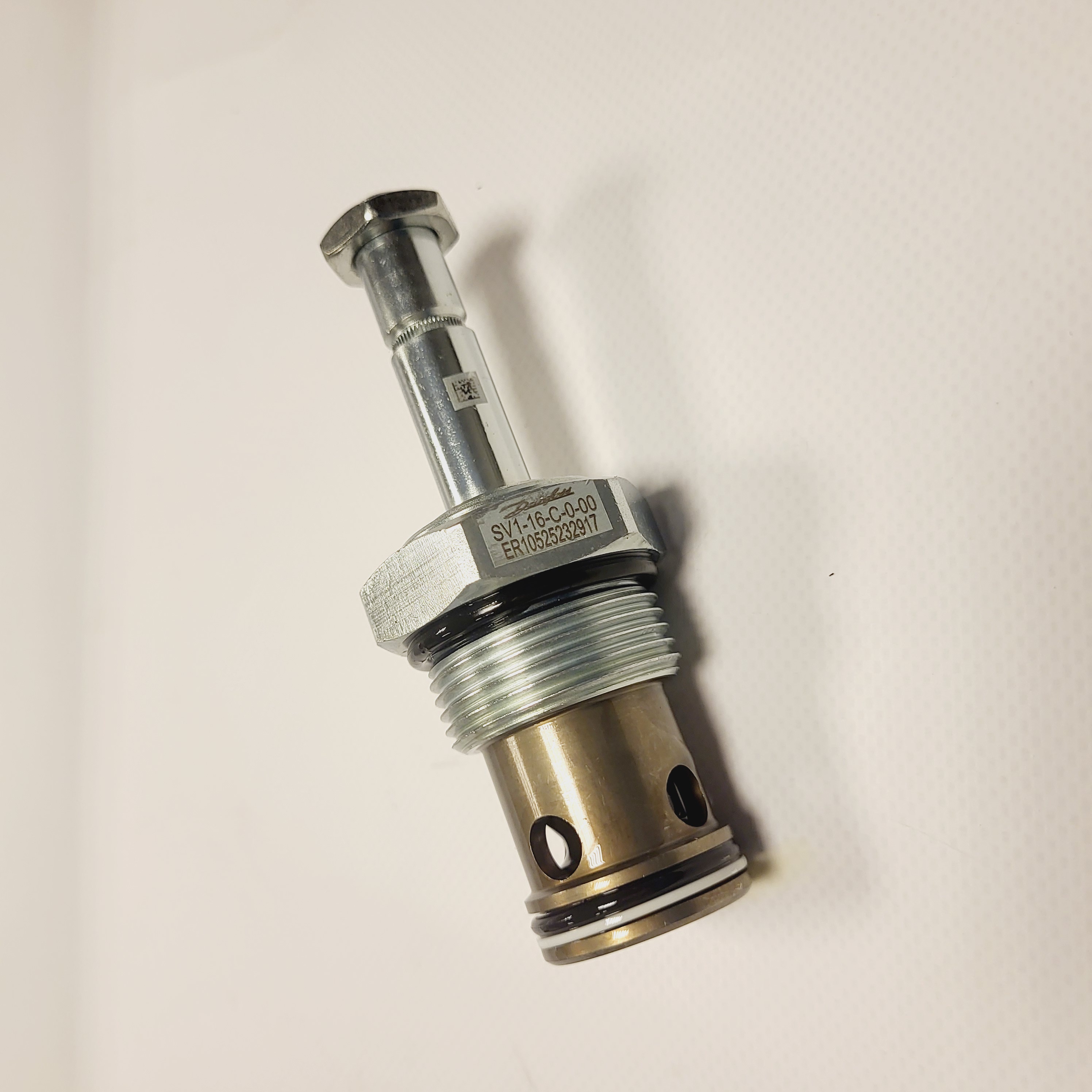
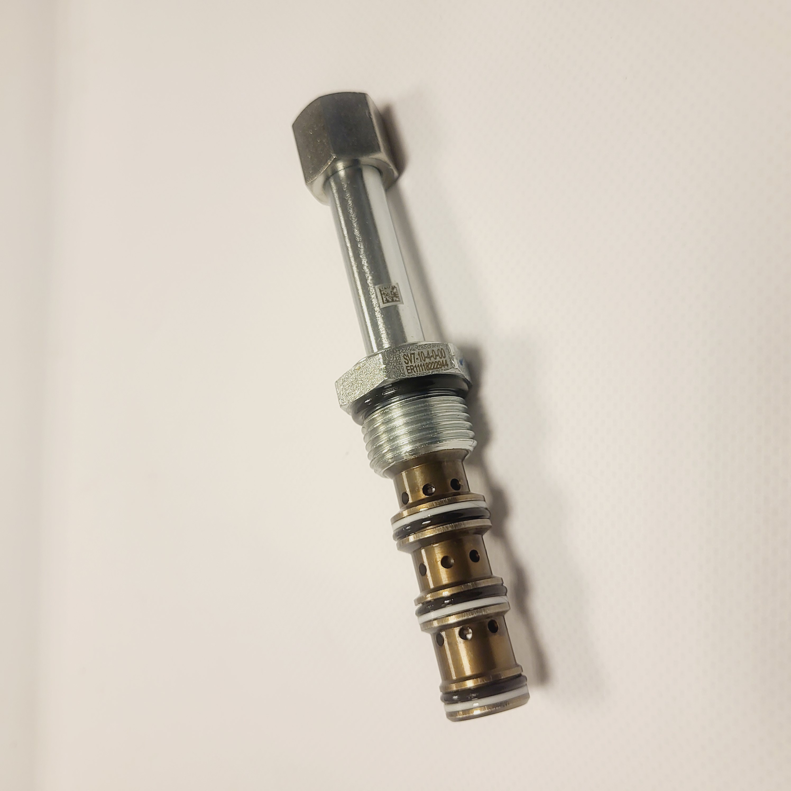
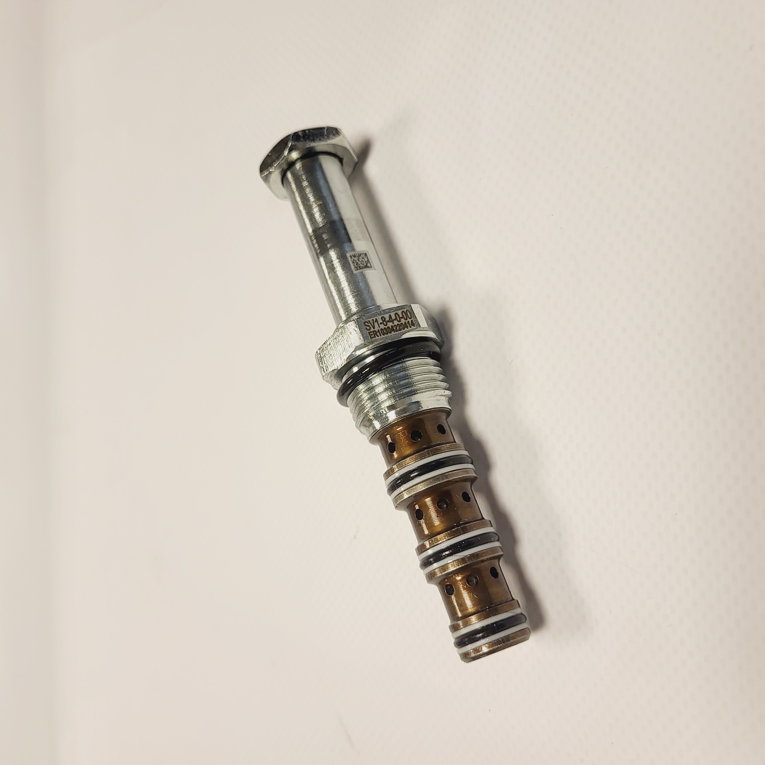
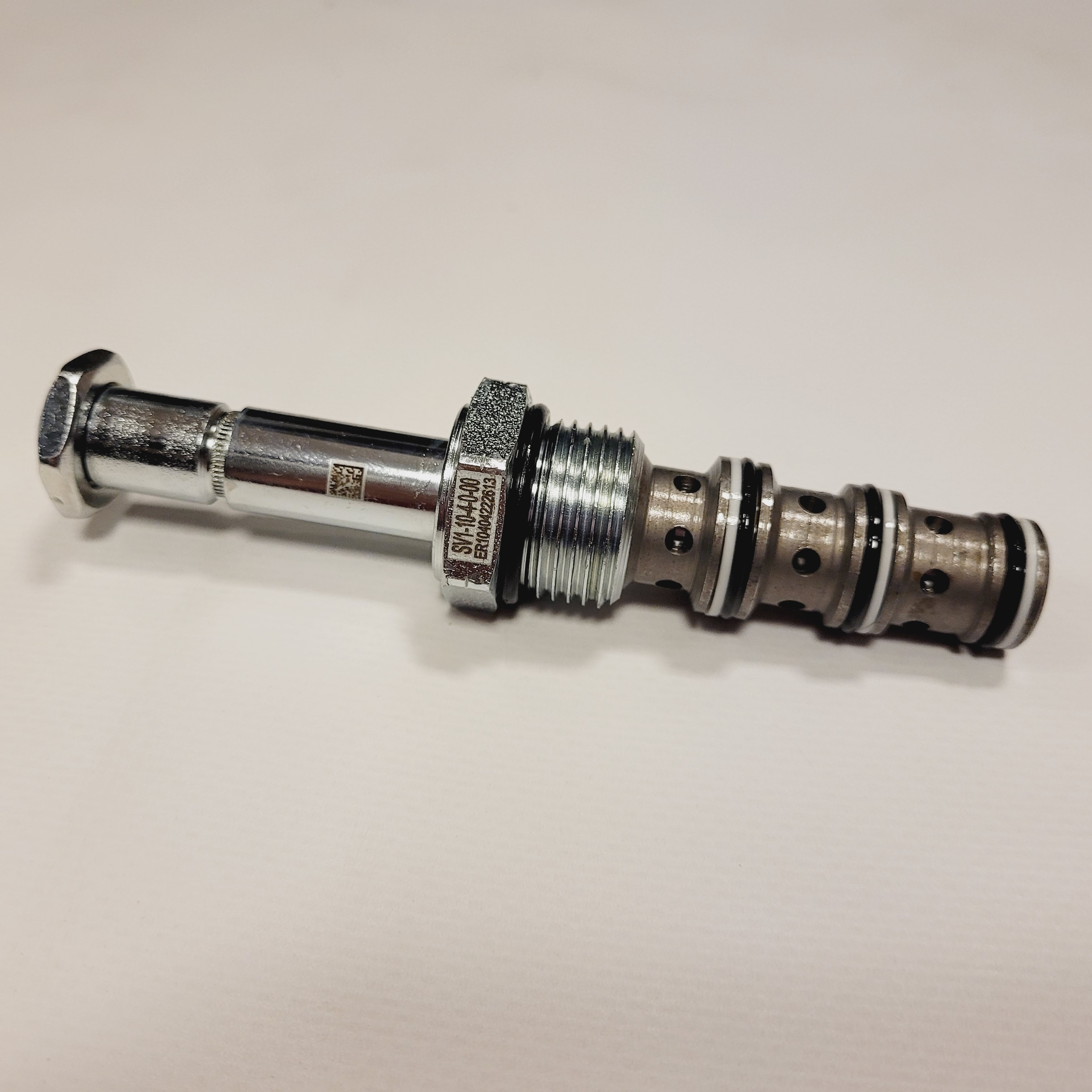
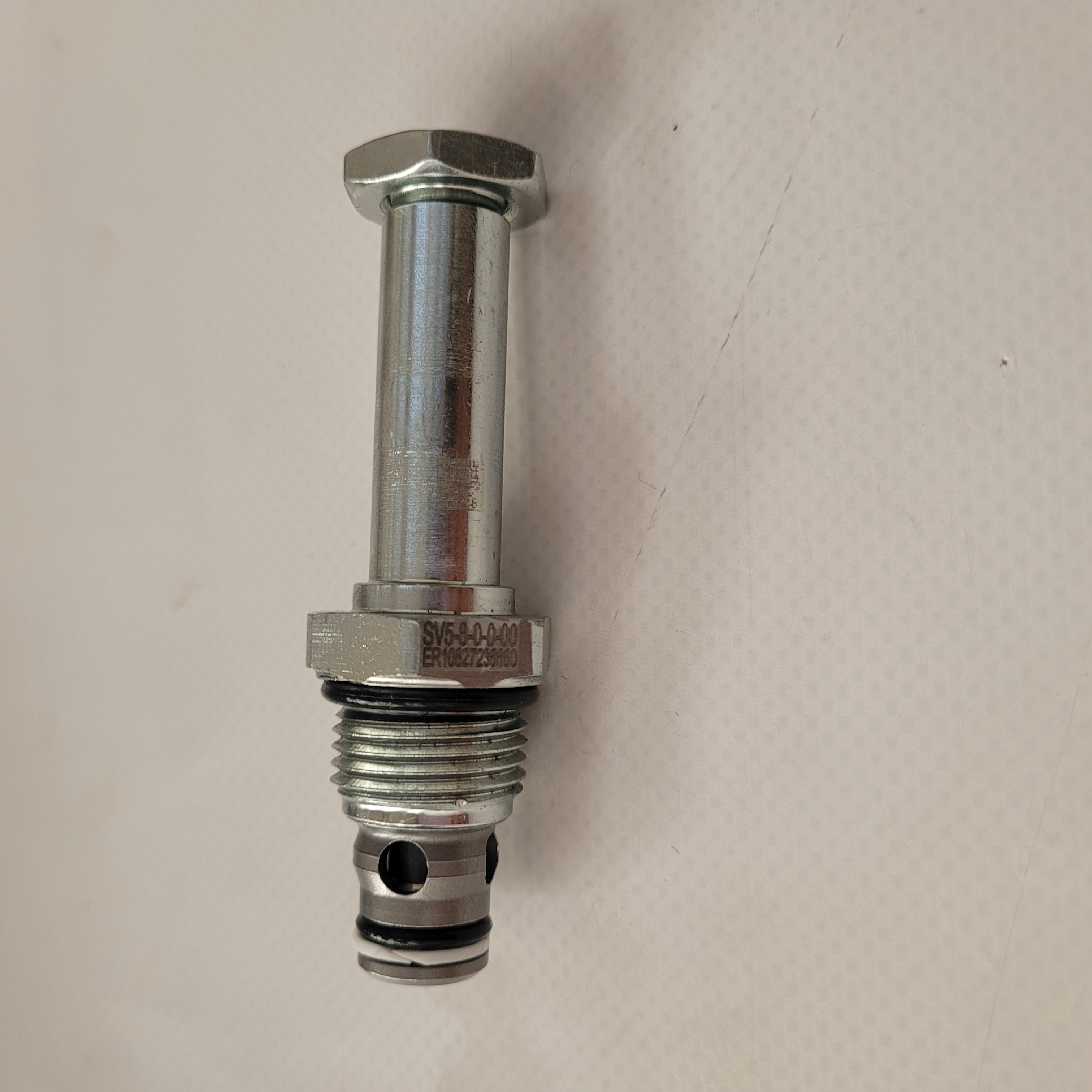
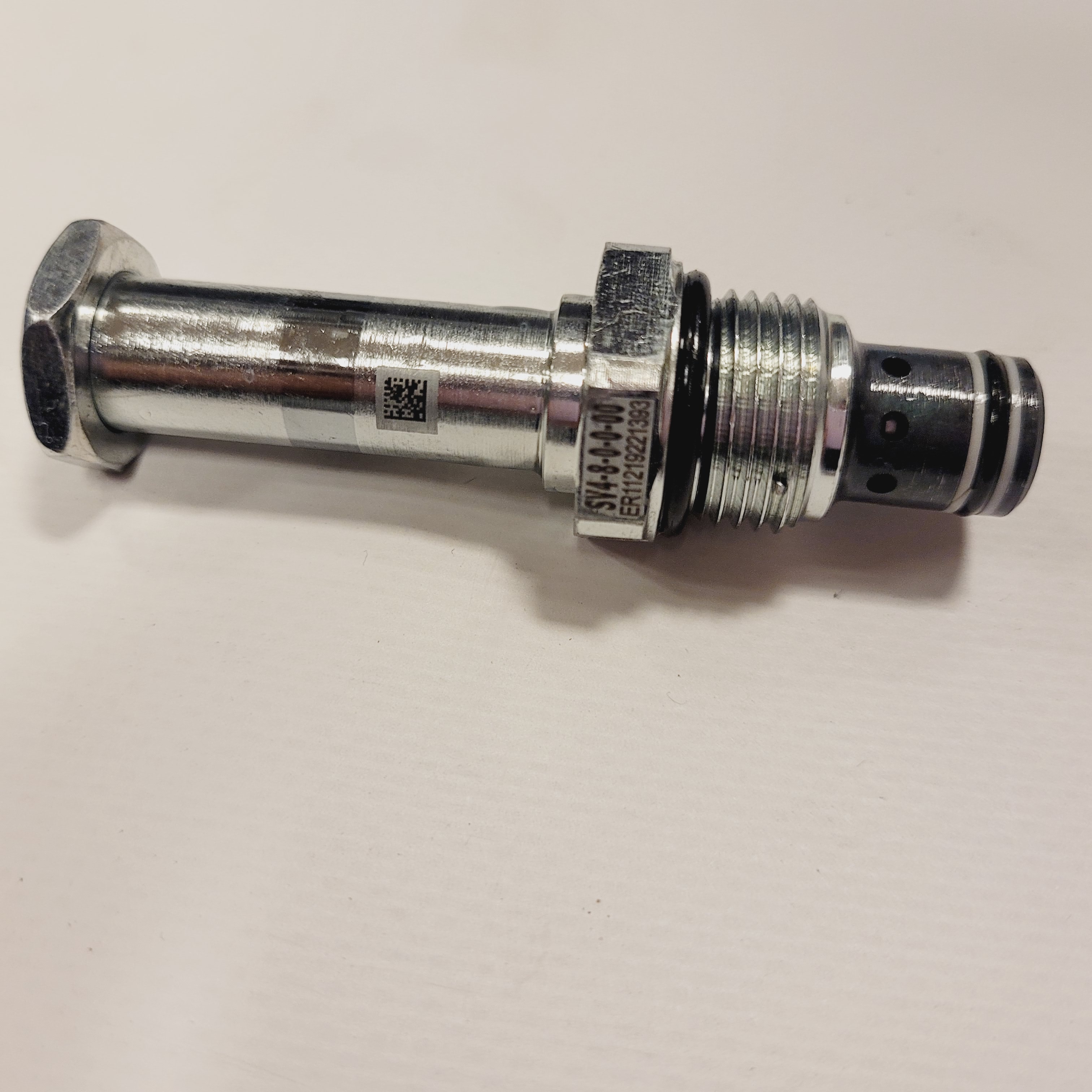
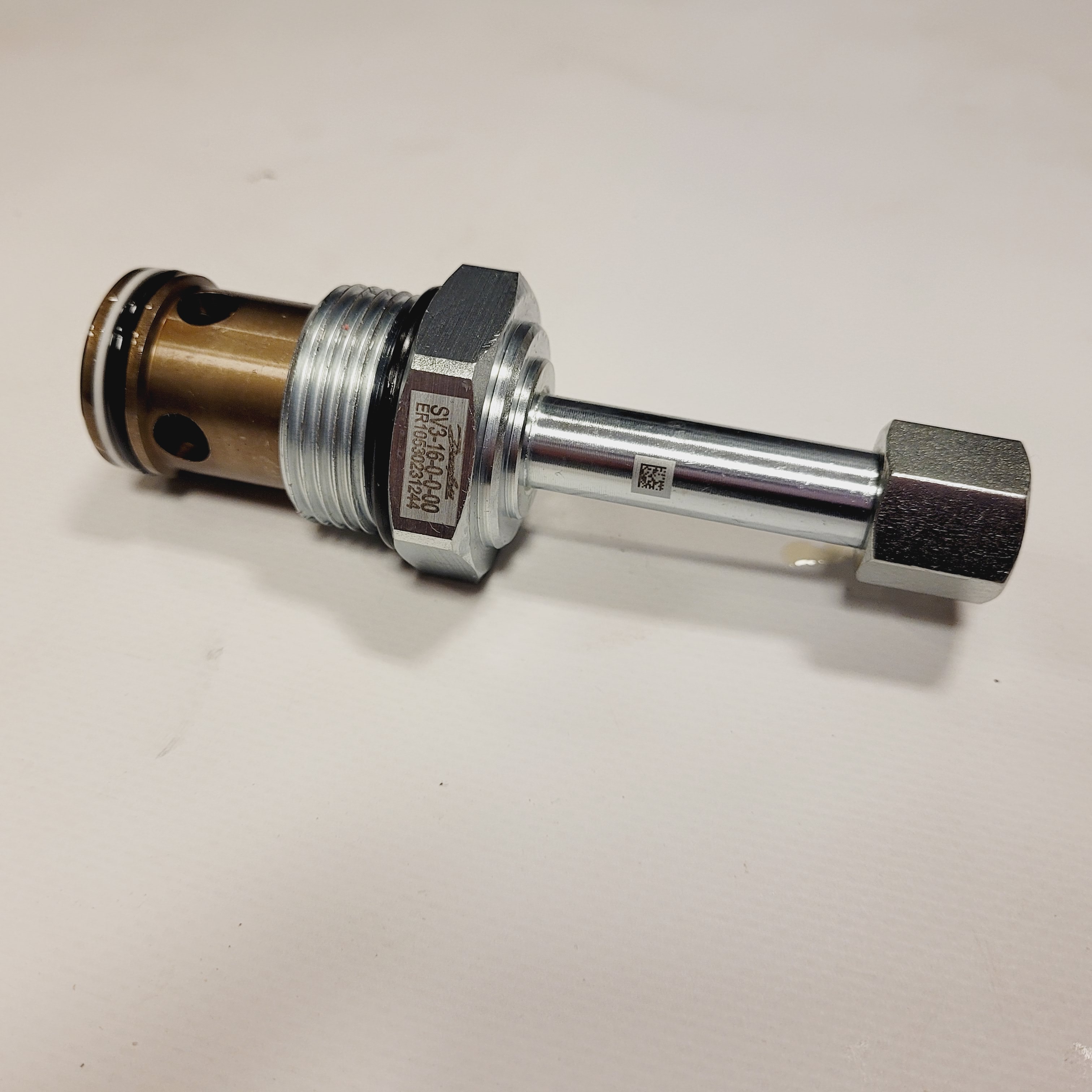
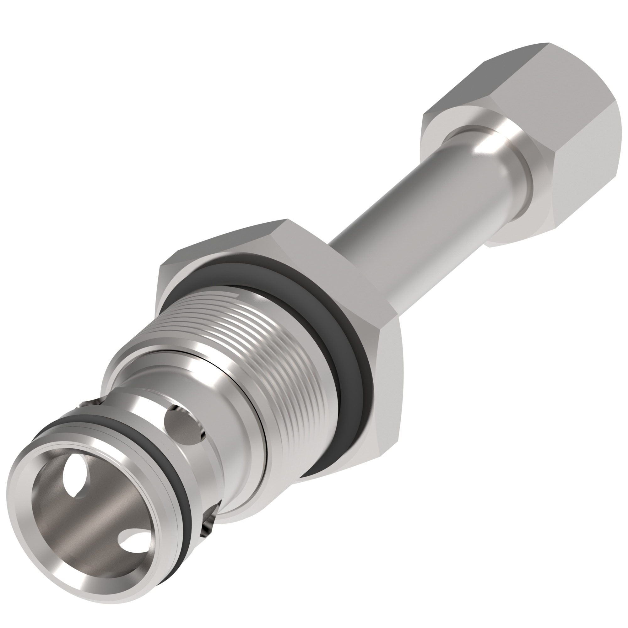
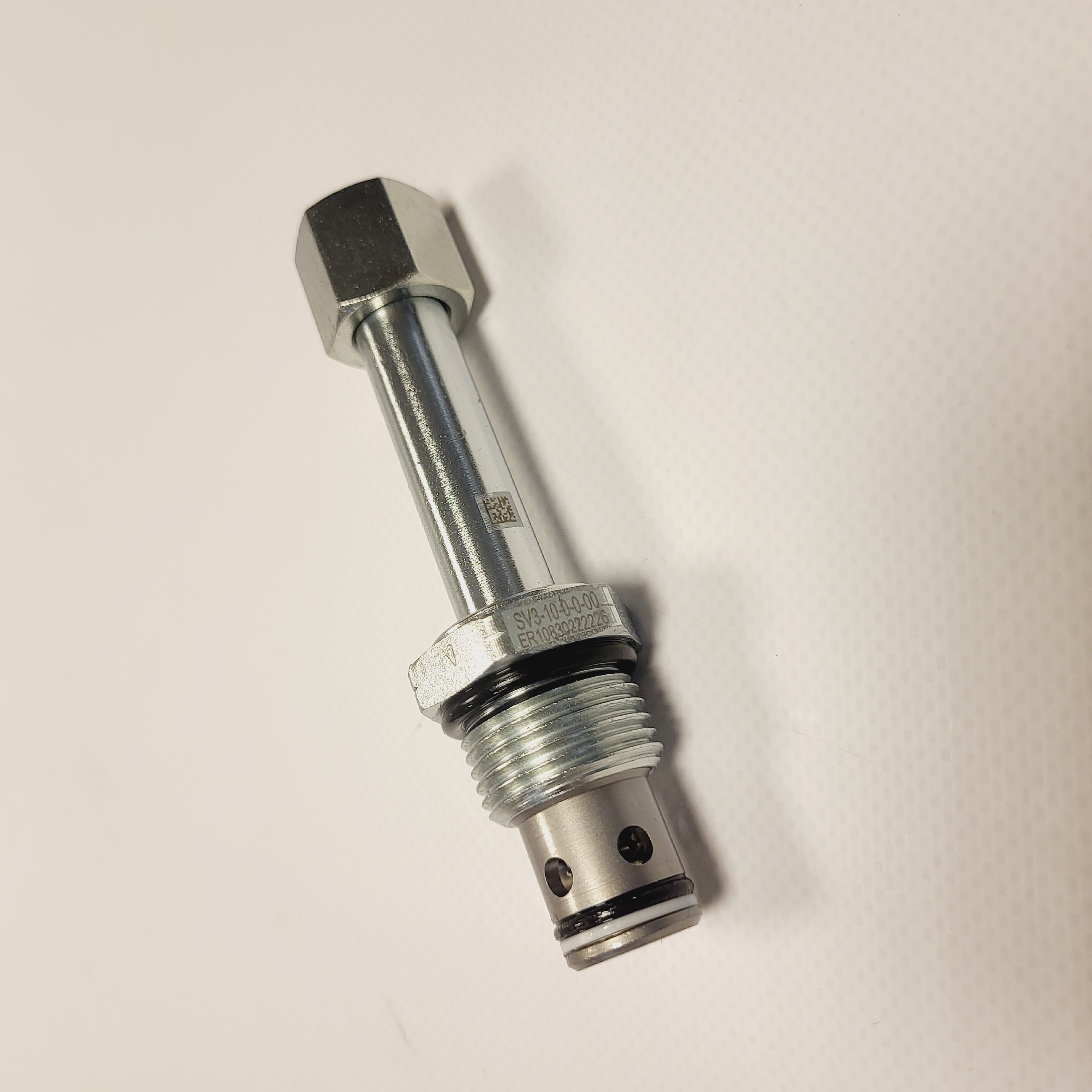
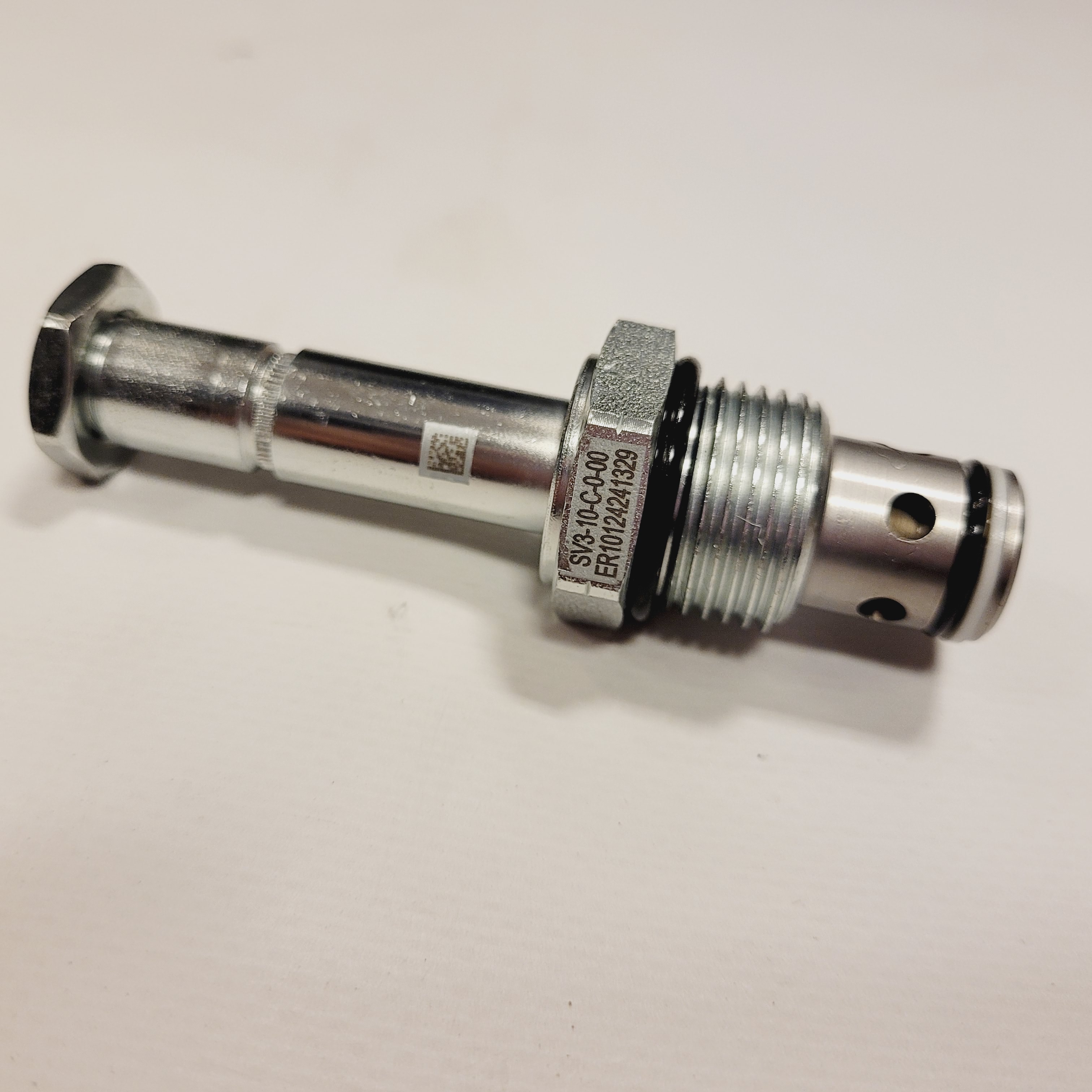
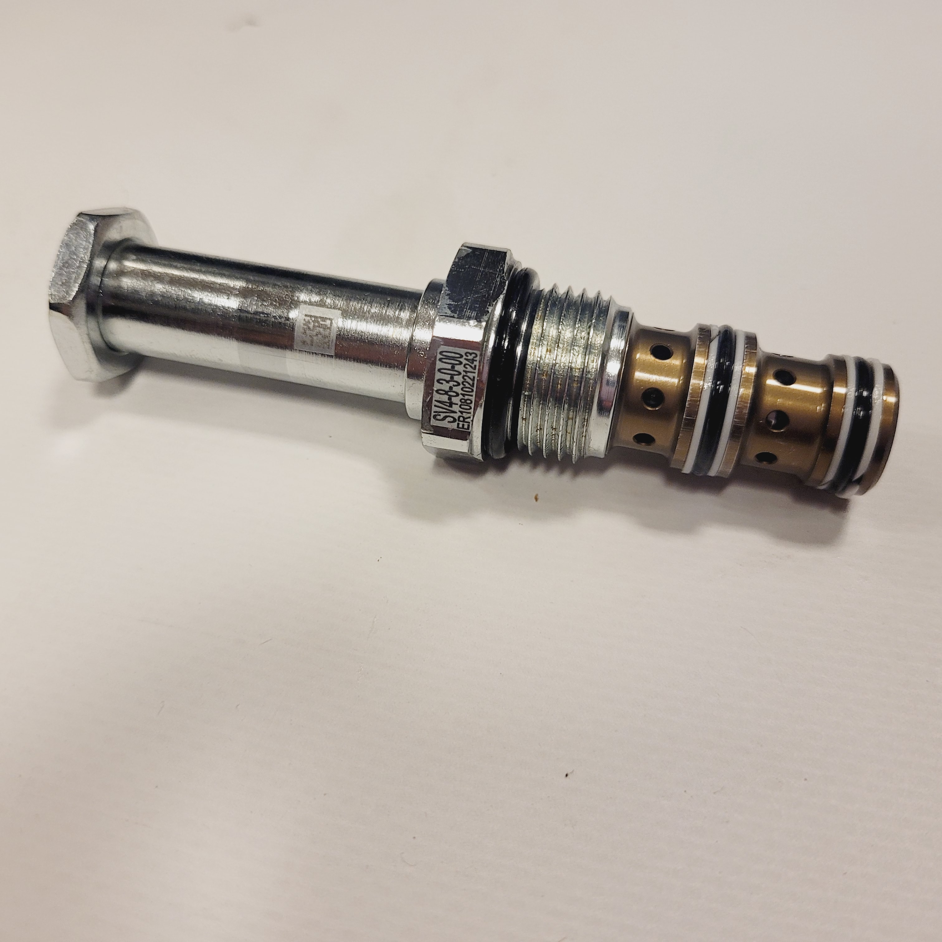
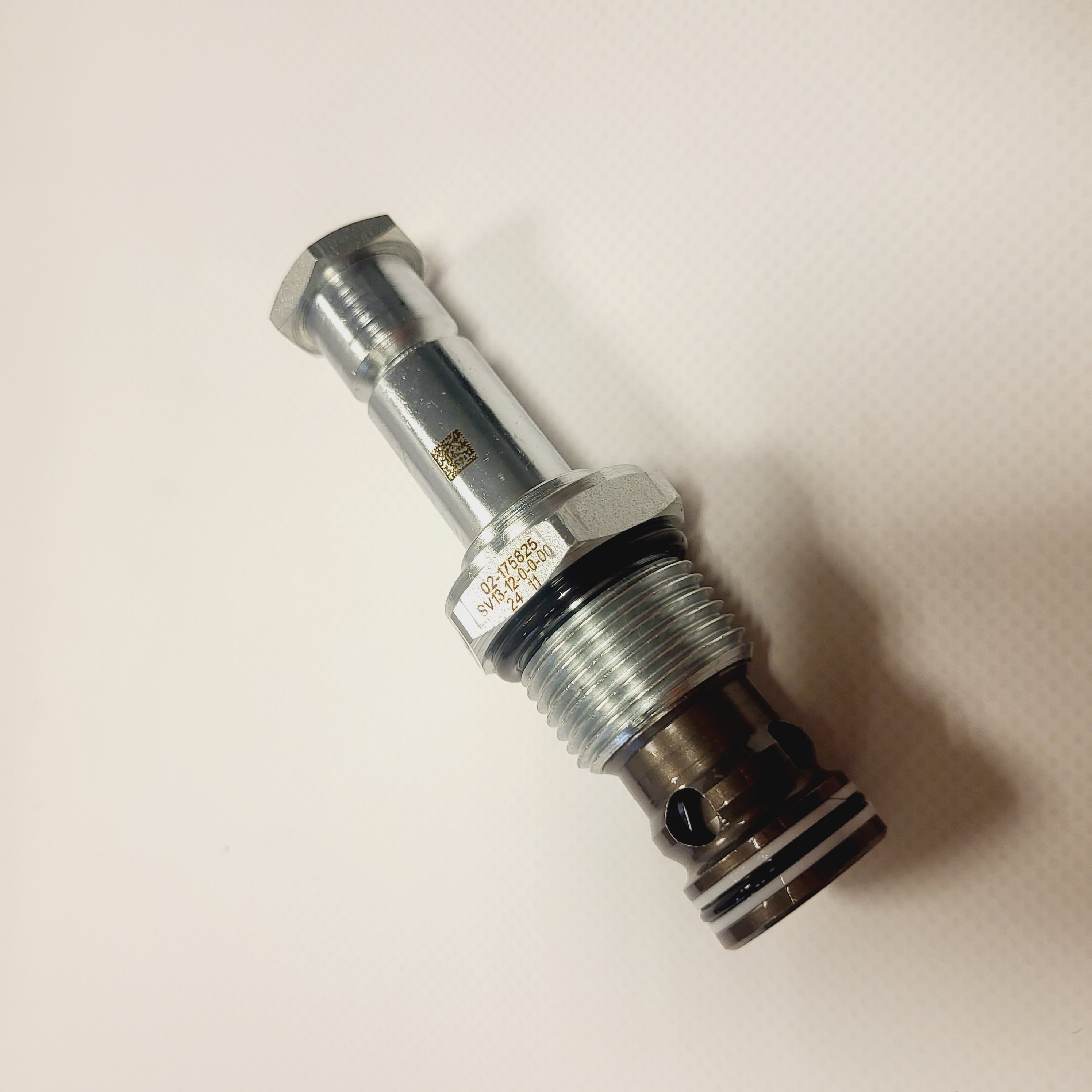
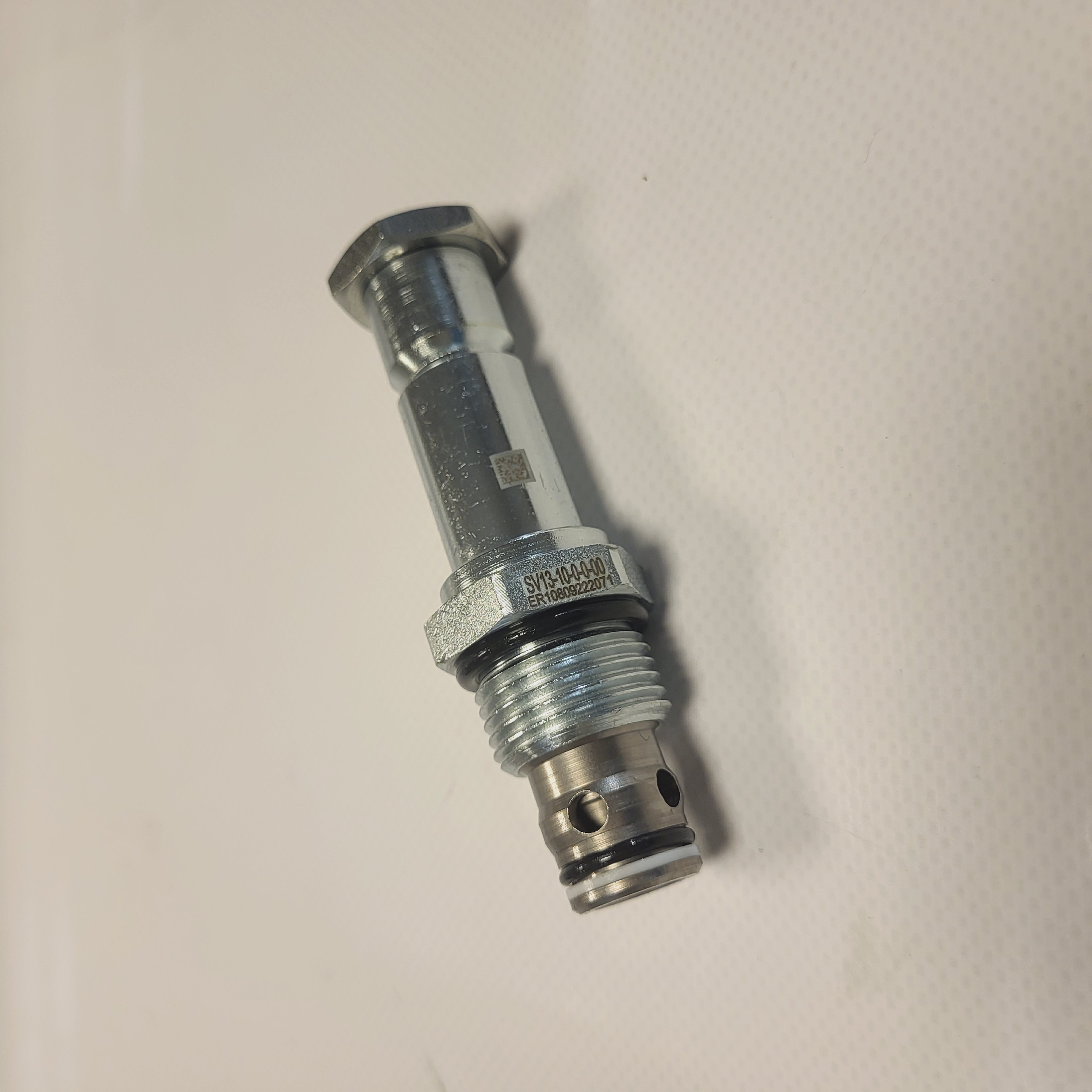
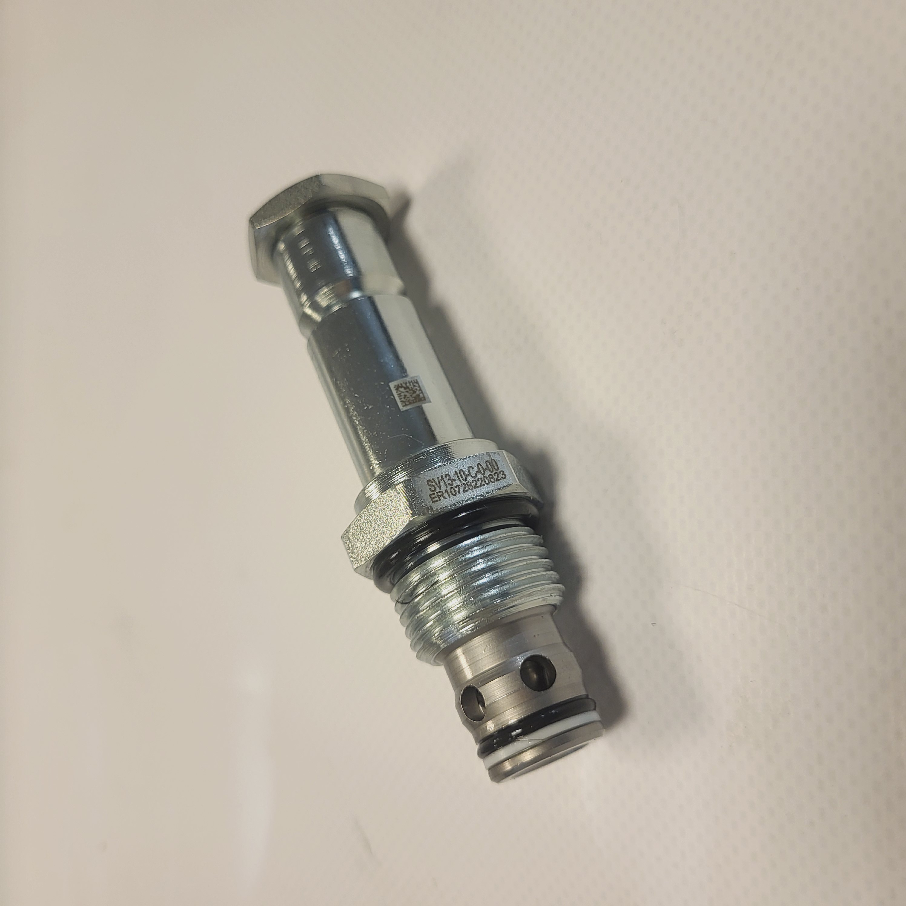
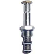
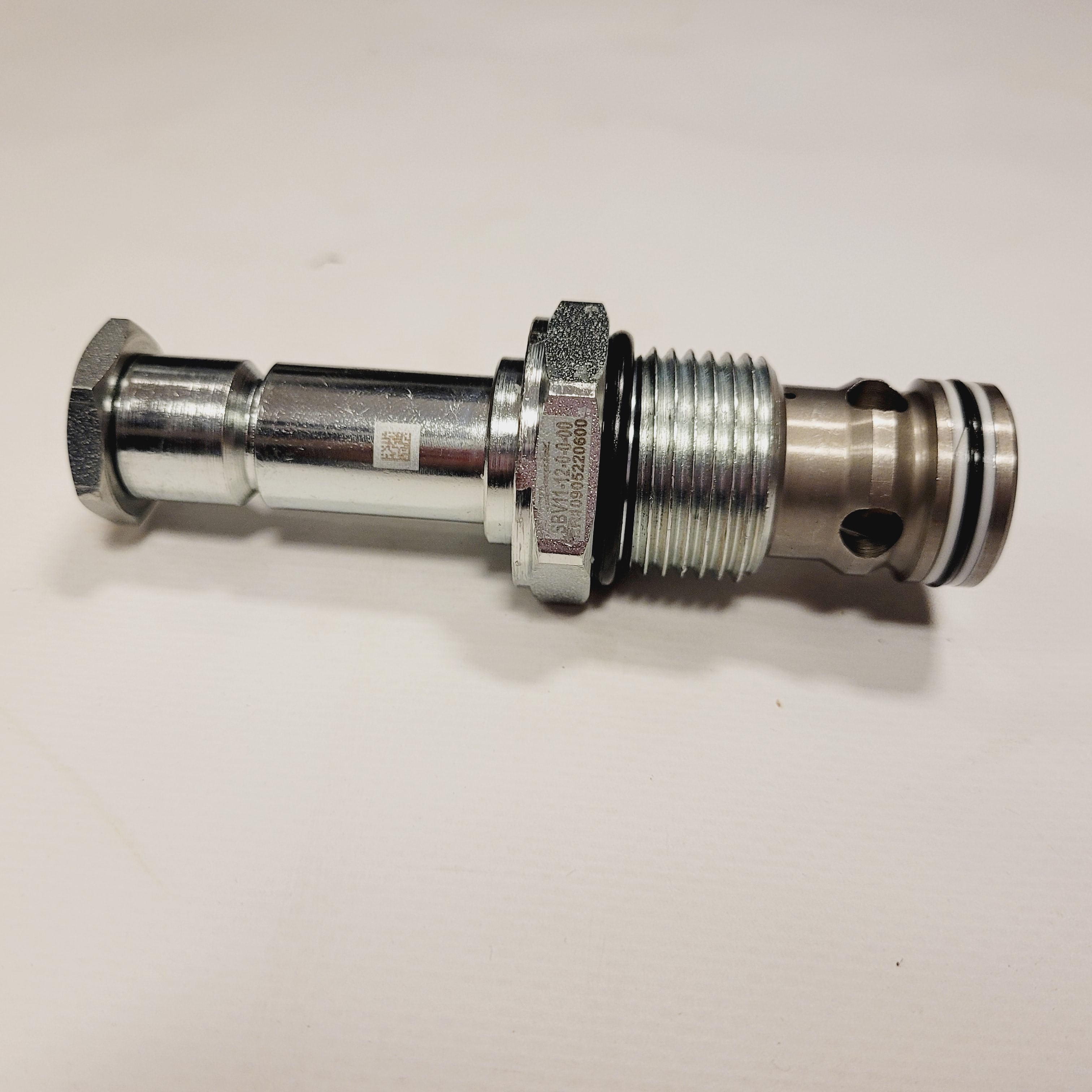
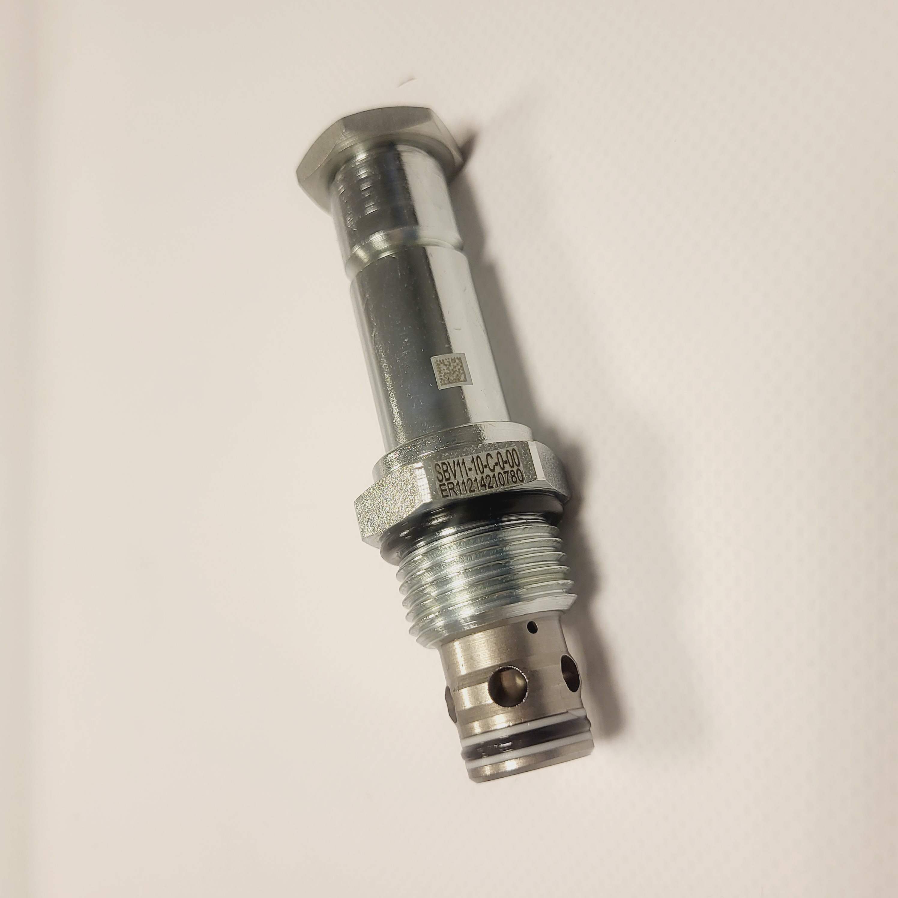
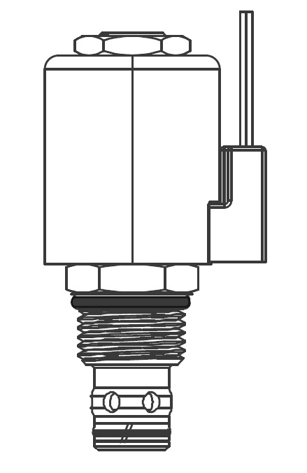
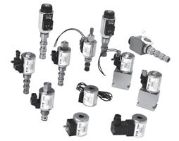
Solenoid cartridge documentation includes Eaton SBV1-10 and SBV11-10, SV3-10 and SV13-10, and 3-way SV4-10 arrangements. Check the hydraulic symbol, normal position, permitted flow direction and coil specification for the exact code.
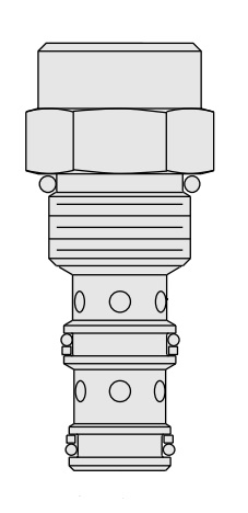
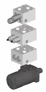
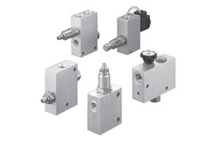
Referenced assemblies for orbital motor applications include Eaton 1CLLROMP150 and CEOMP35. Confirm compatibility with the motor, mounting interface, operating pressures and required load-control behaviour.
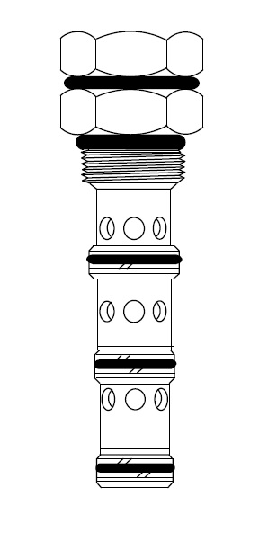
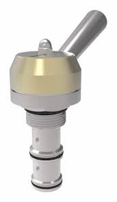
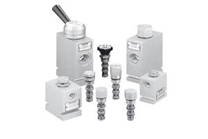
Eaton MRV and MSV references cover manually operated directional valves for suitable control or override functions. PTS1-10 logic valves may be combined with other components to provide the required circuit behaviour. Check the complete hydraulic schematic before selection.
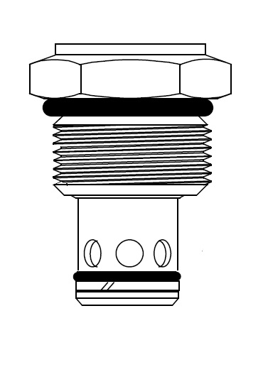
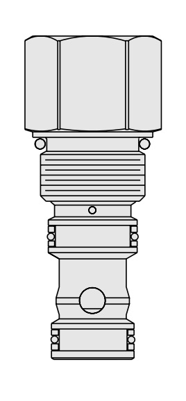
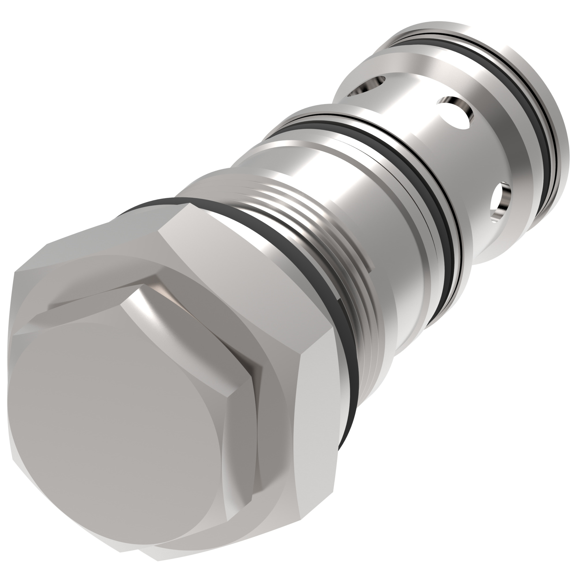
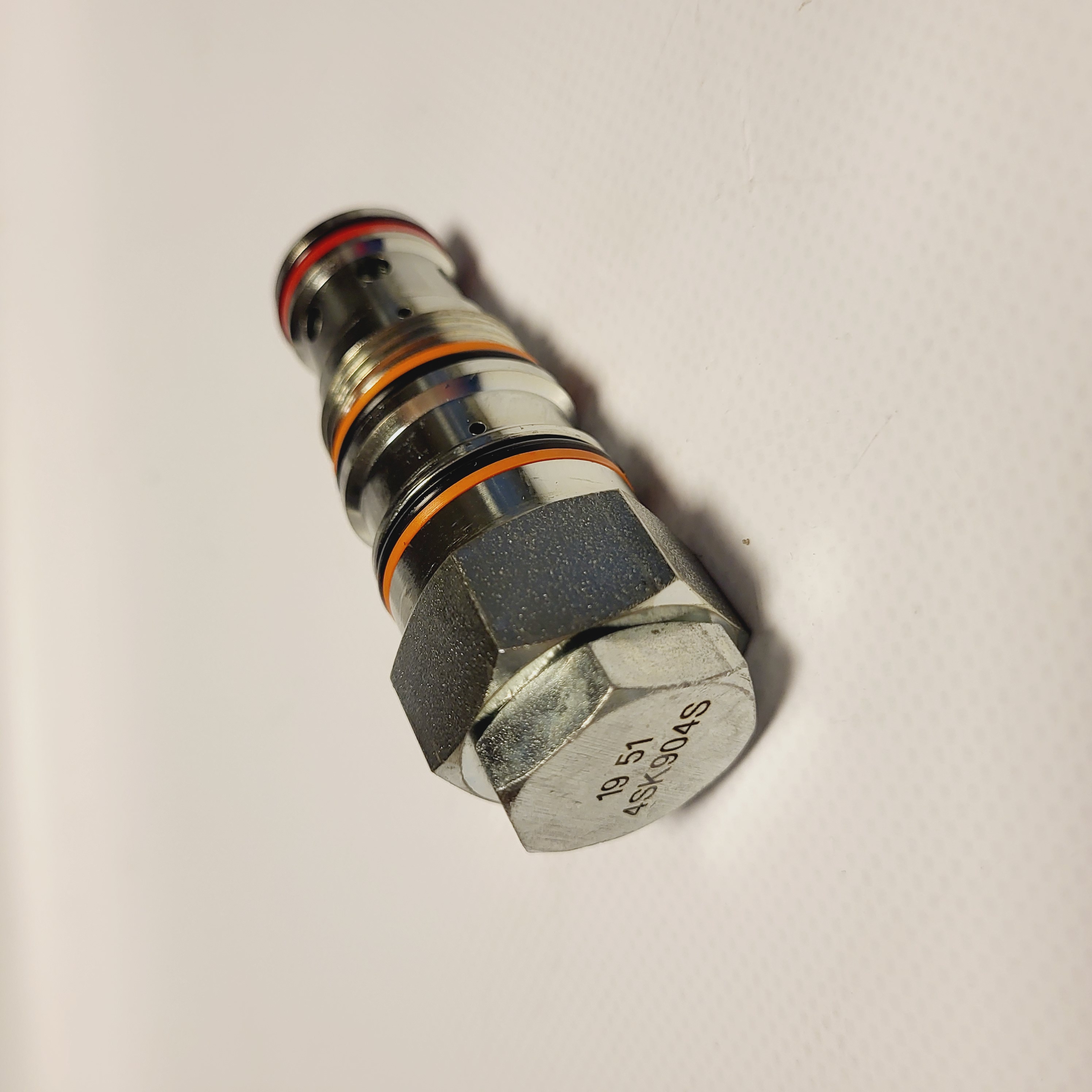
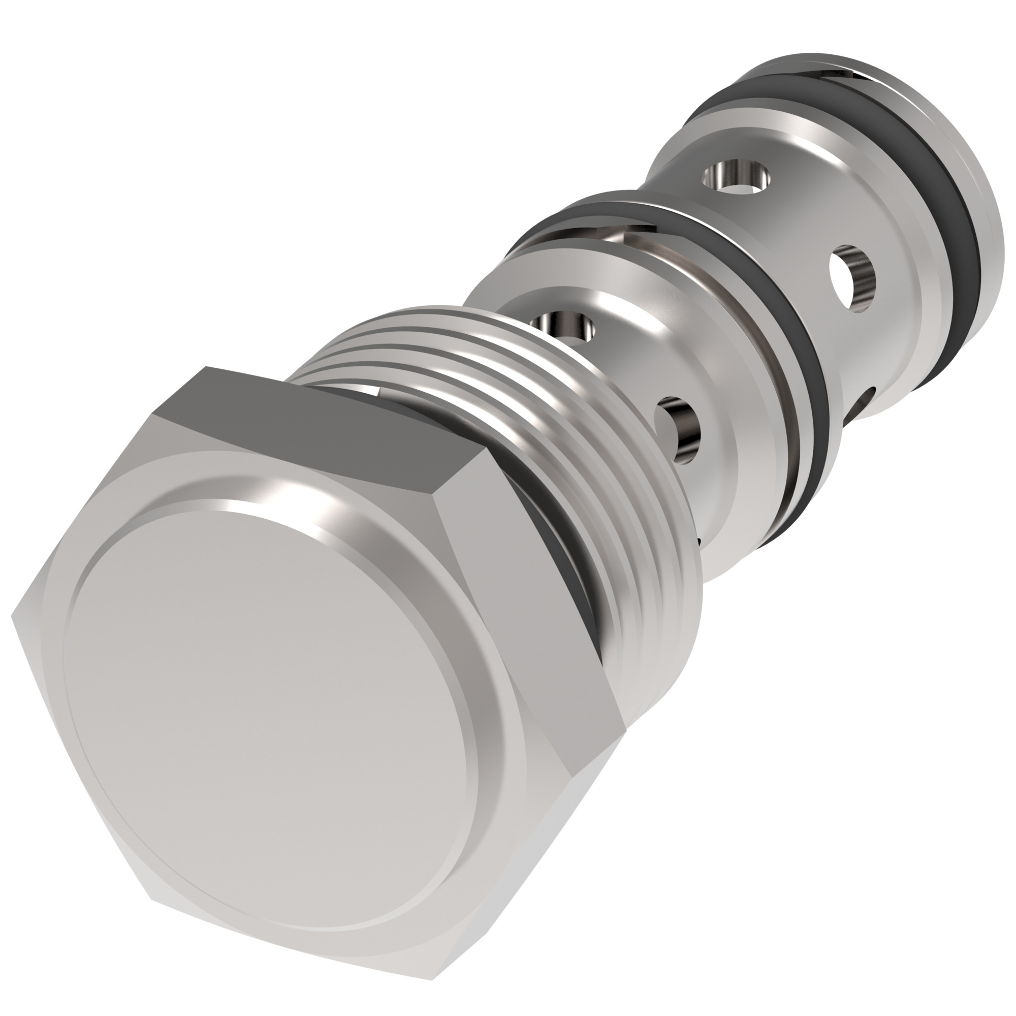
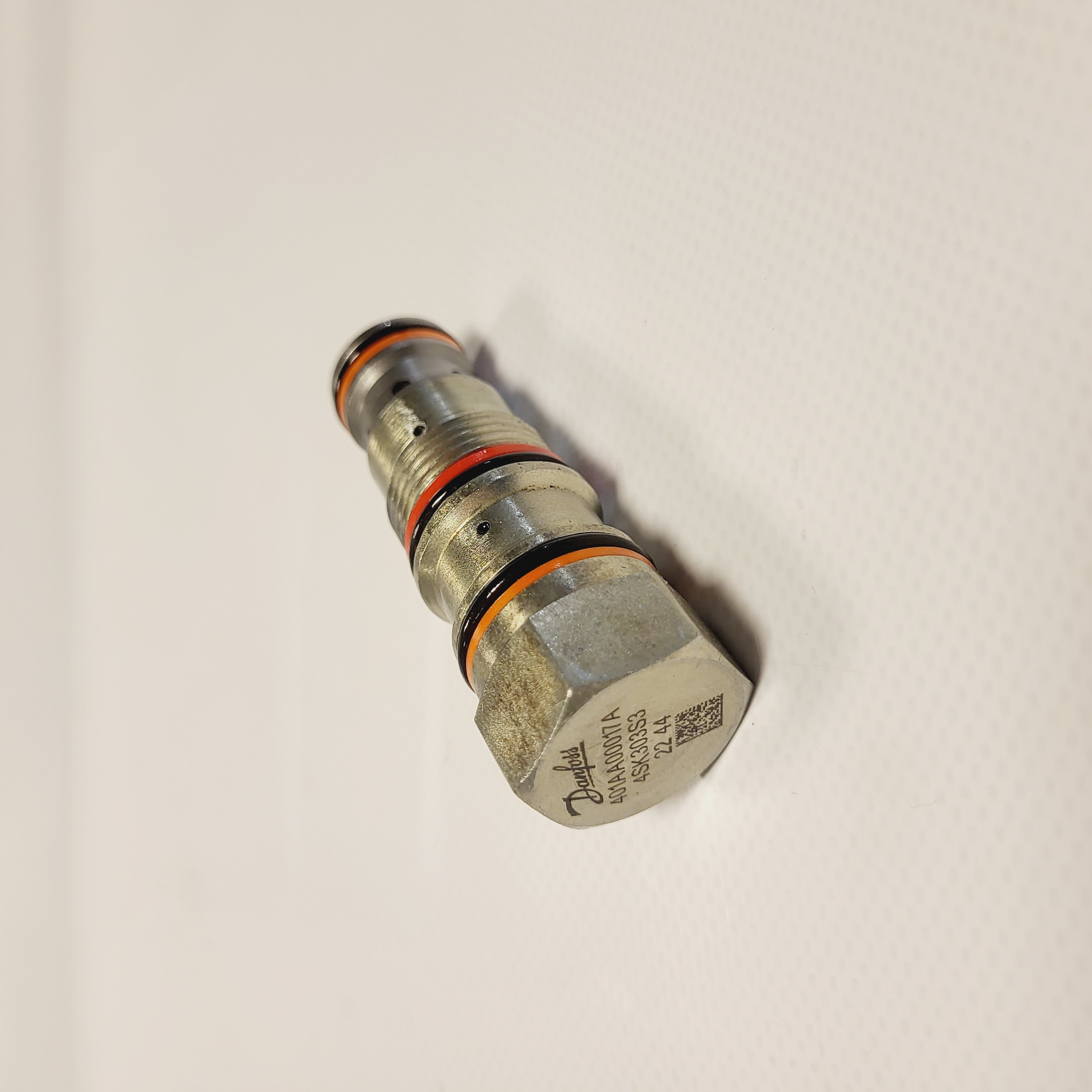
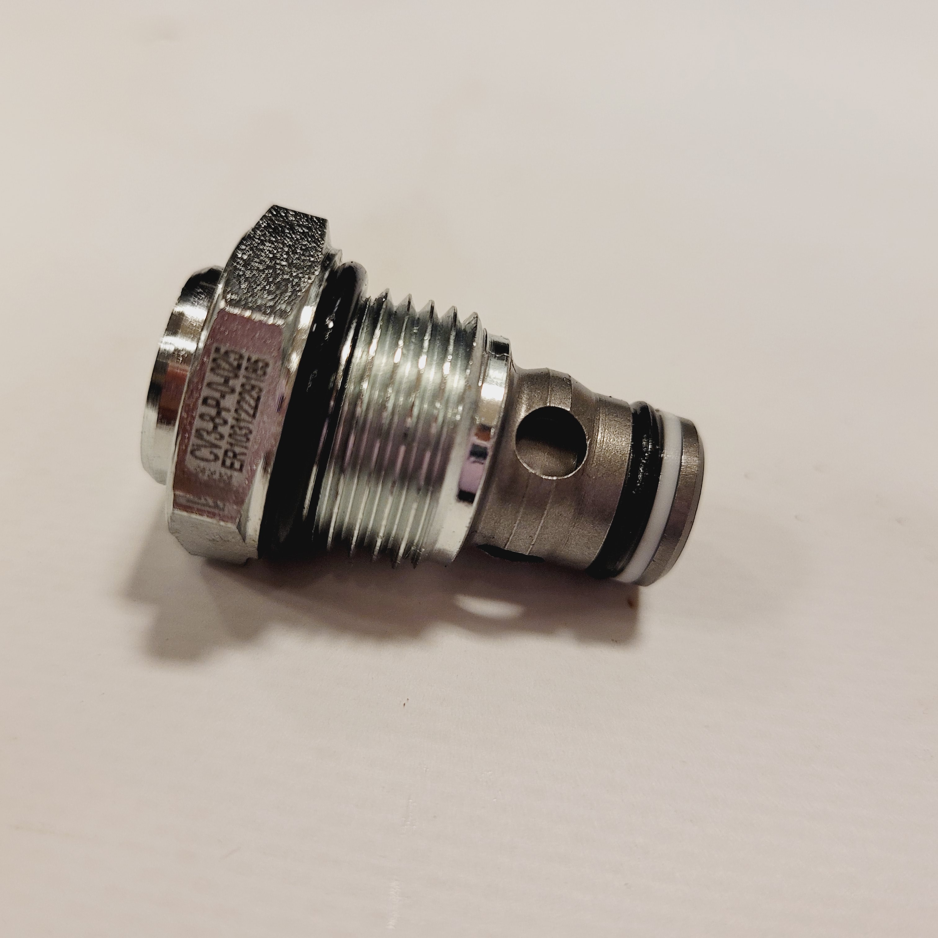
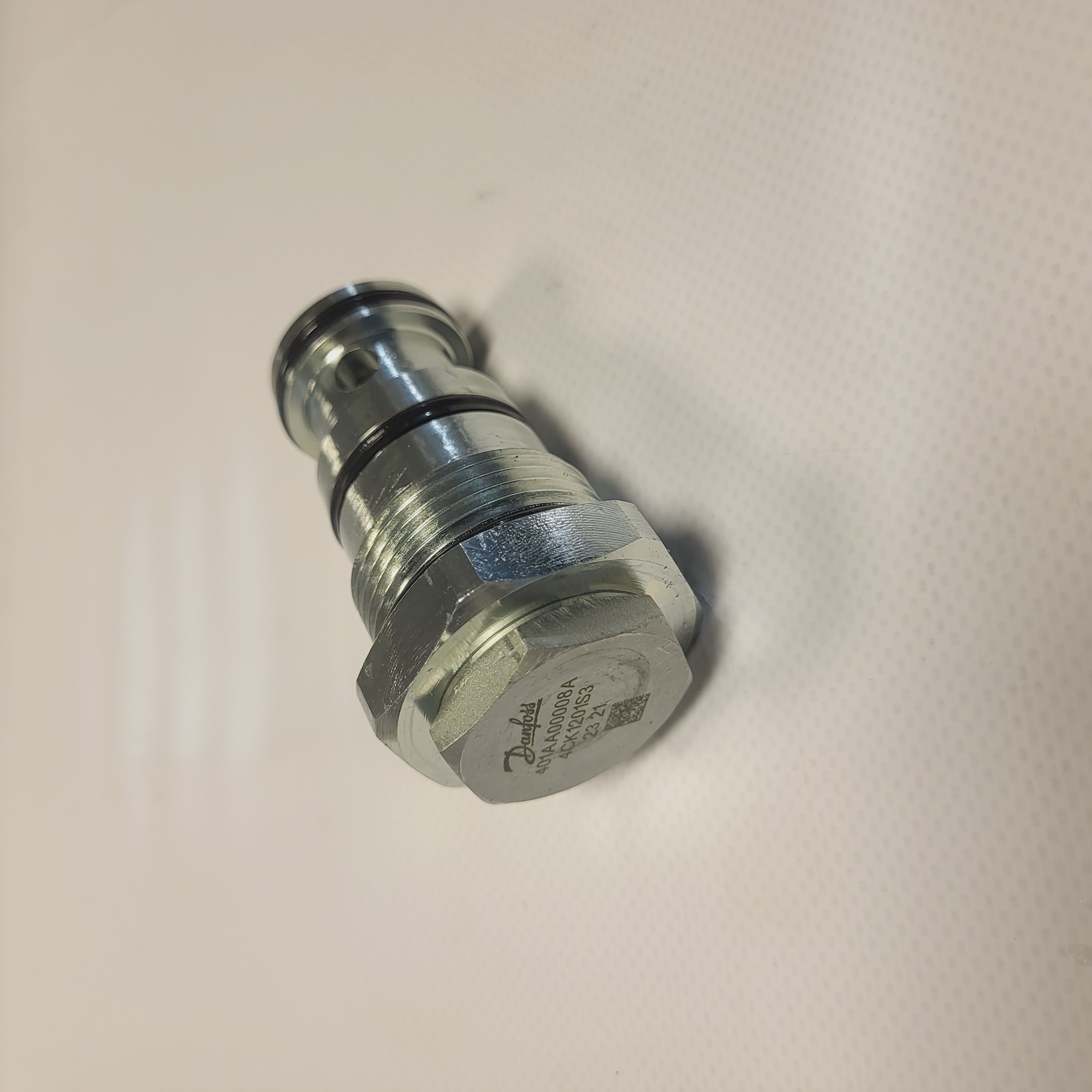
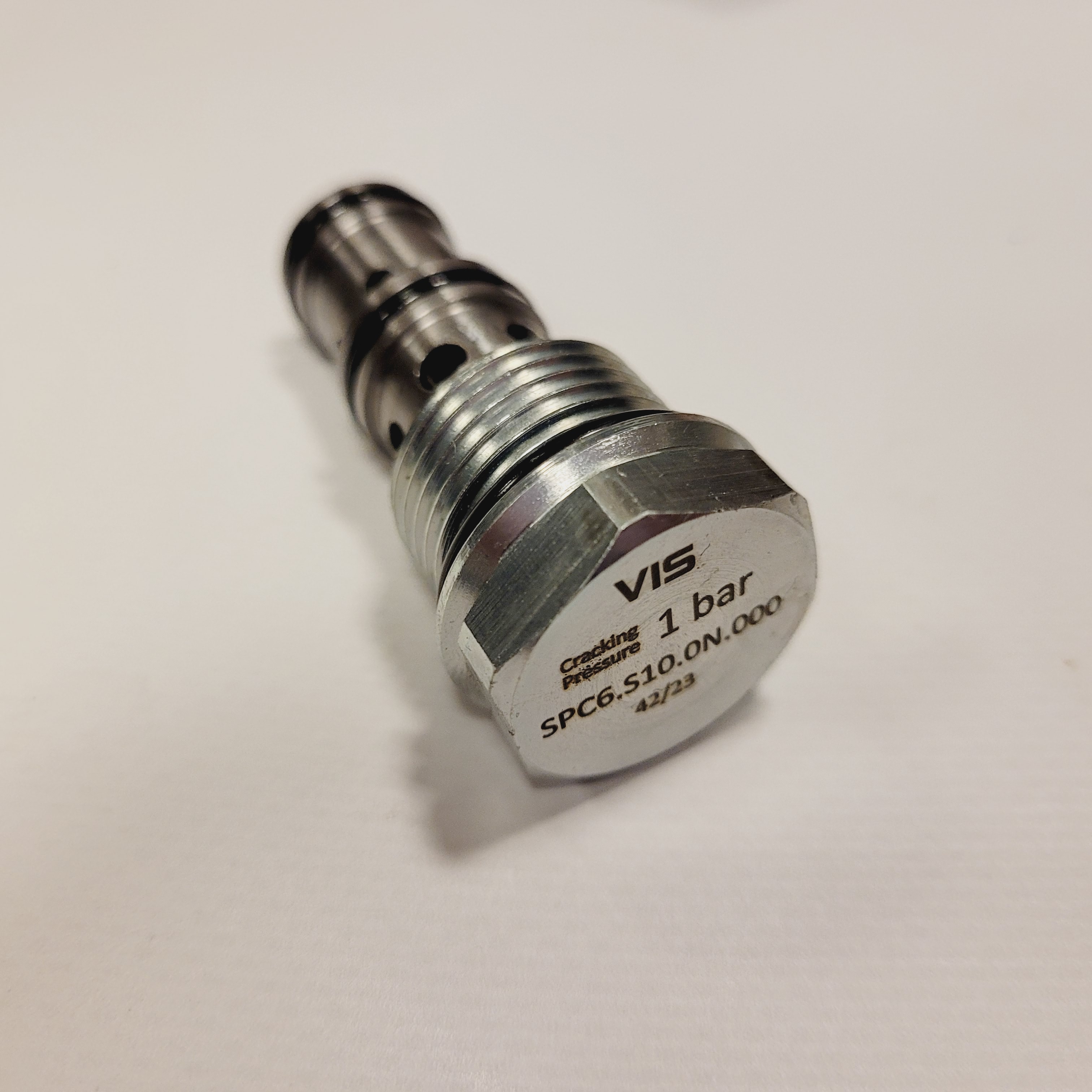
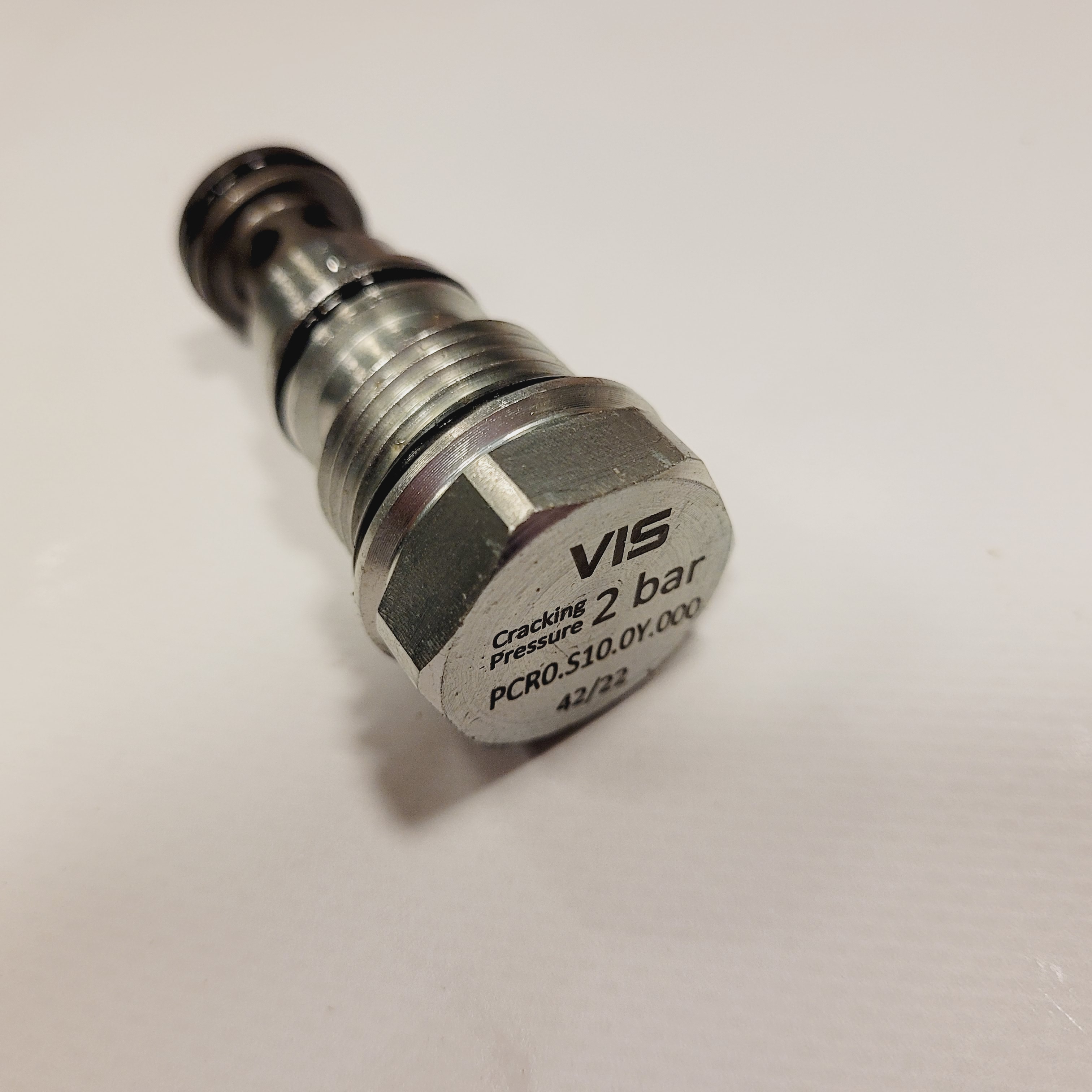
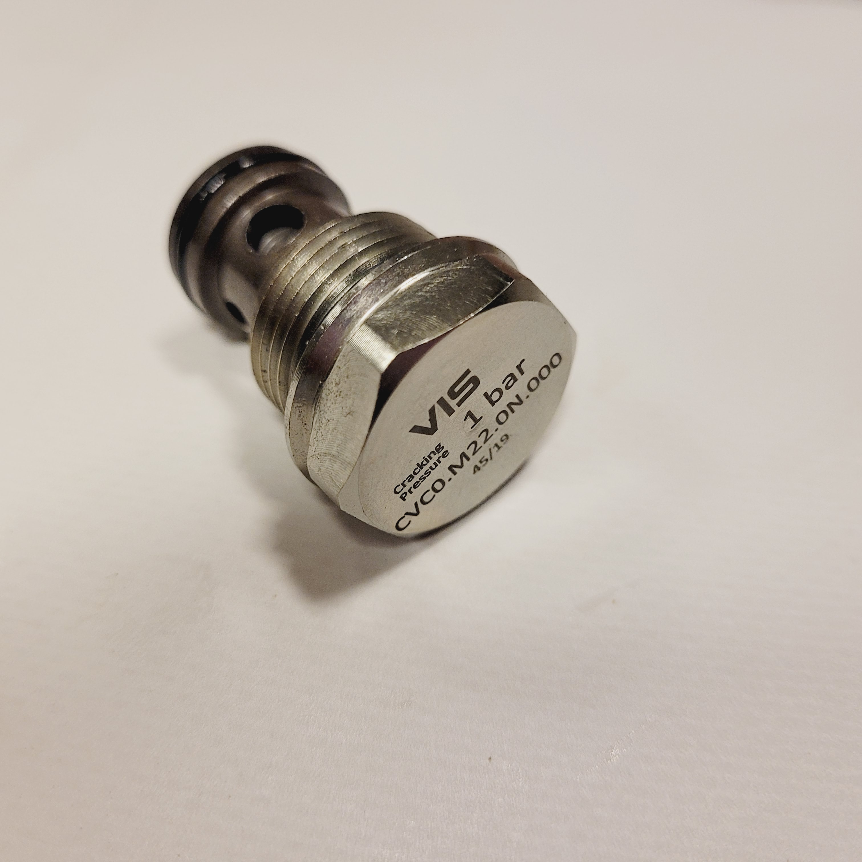
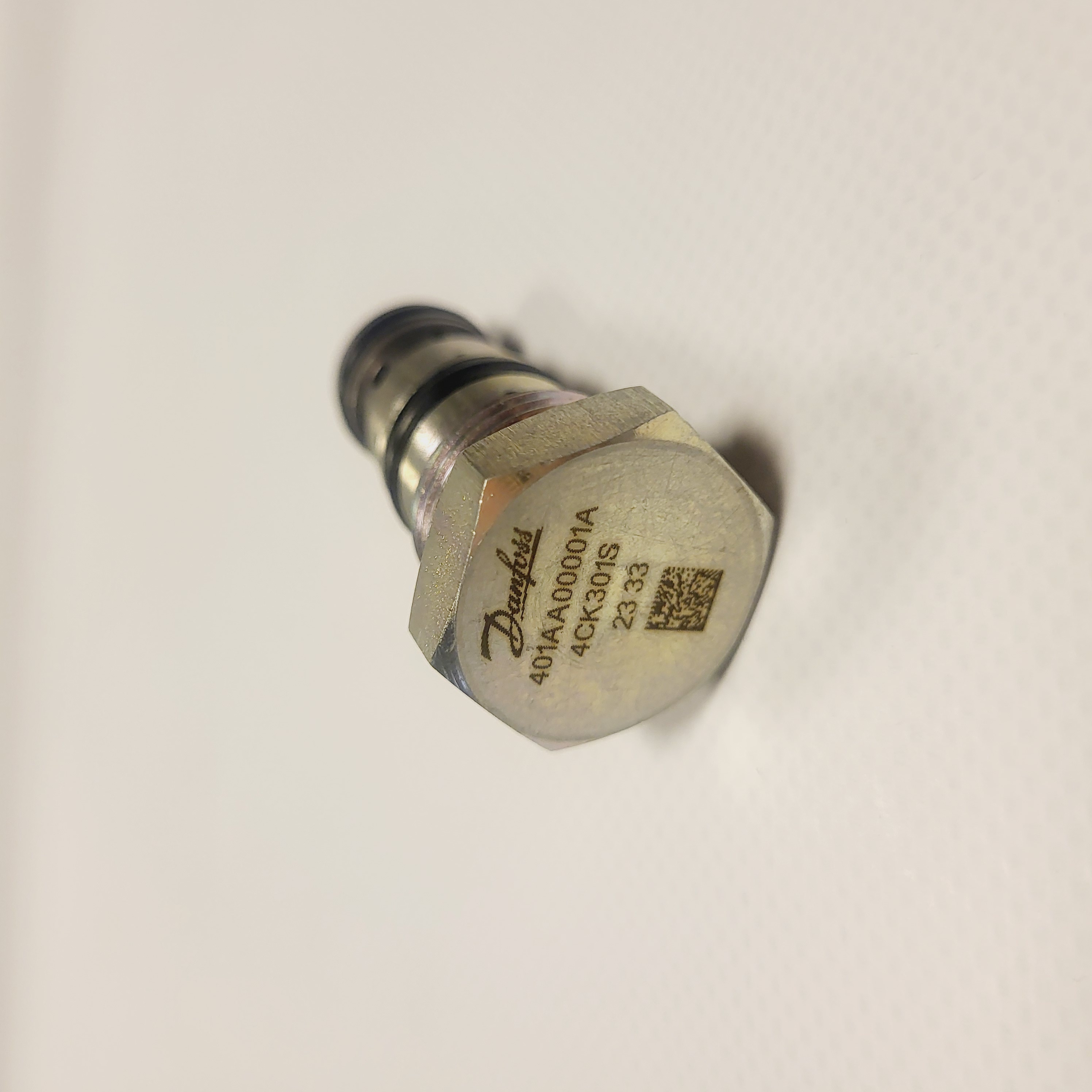
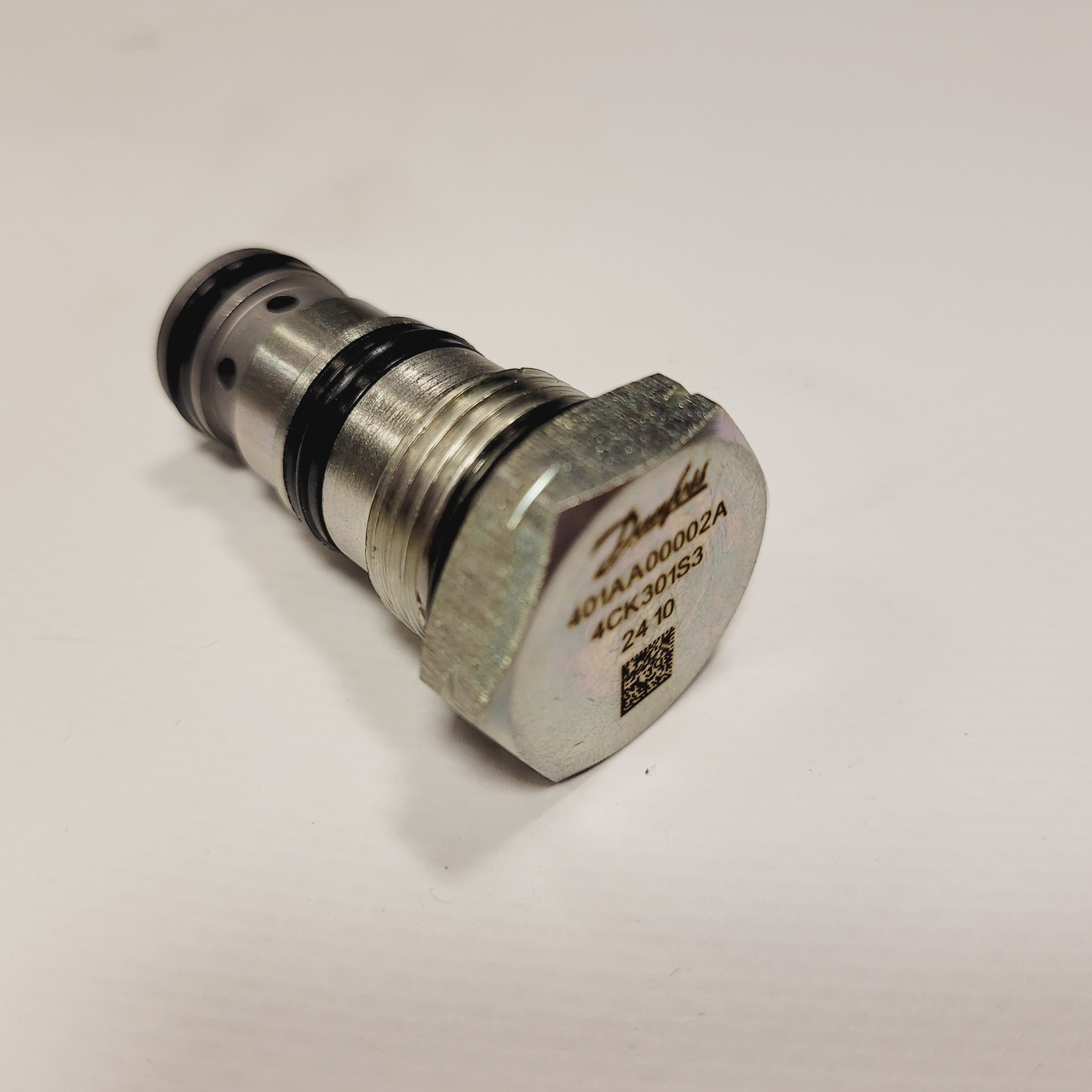
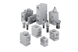
Check valves permit flow in one direction and block the reverse direction according to their specification. References include Eaton CV3-10 and CV13-10, alongside pilot-operated 4CK30 and 4CK90 designs. The circuit function, cracking pressure, leakage and pilot requirements must match the application.
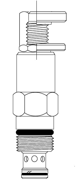
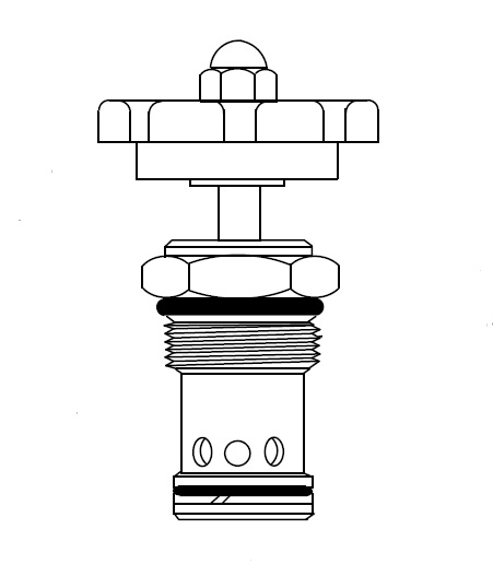
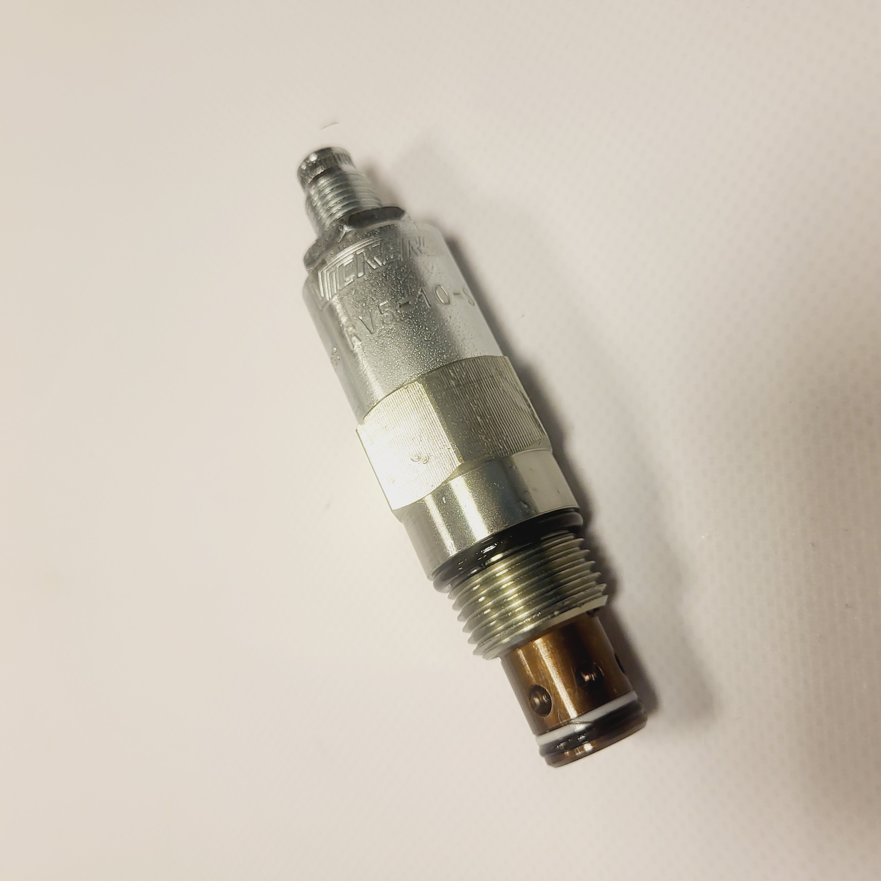
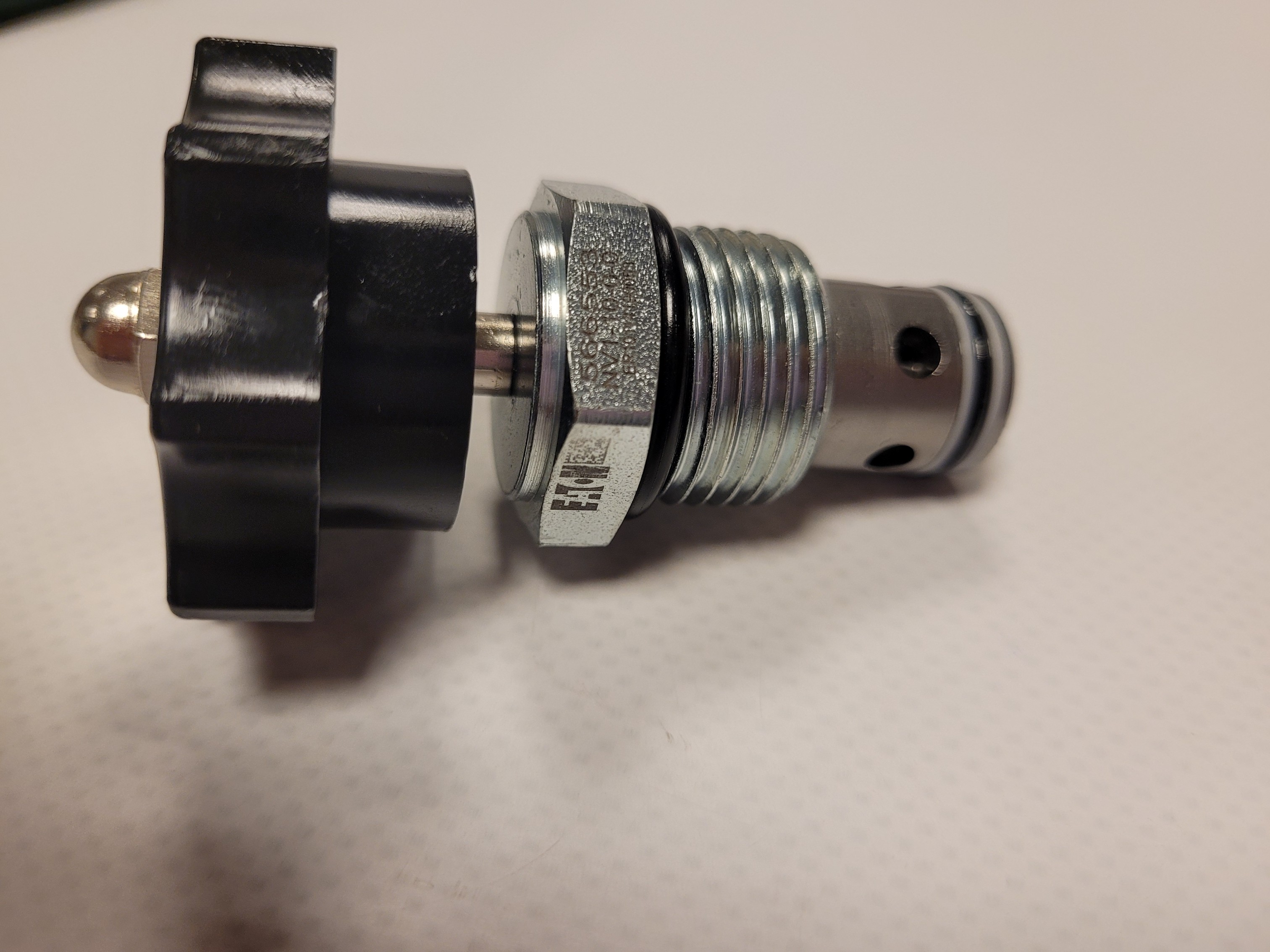

Eaton flow-control references include FR2-10, PFR2-10 and PFR12-10. PCS3-10 and PCS13-10 compensator documentation covers associated pressure-compensation functions. Compare the circuit arrangement, operating range and flow characteristic.
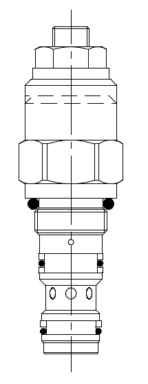
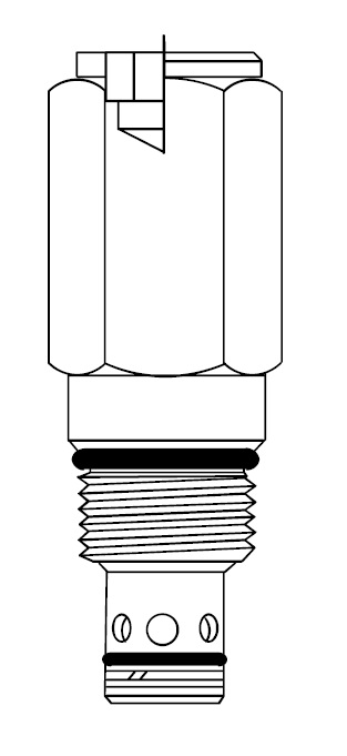
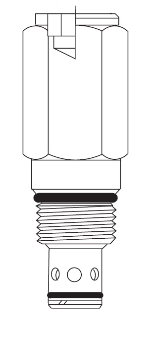
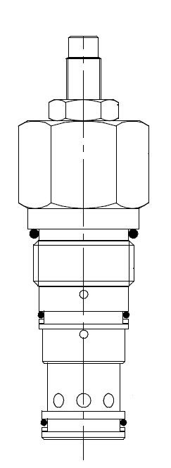
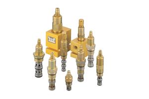
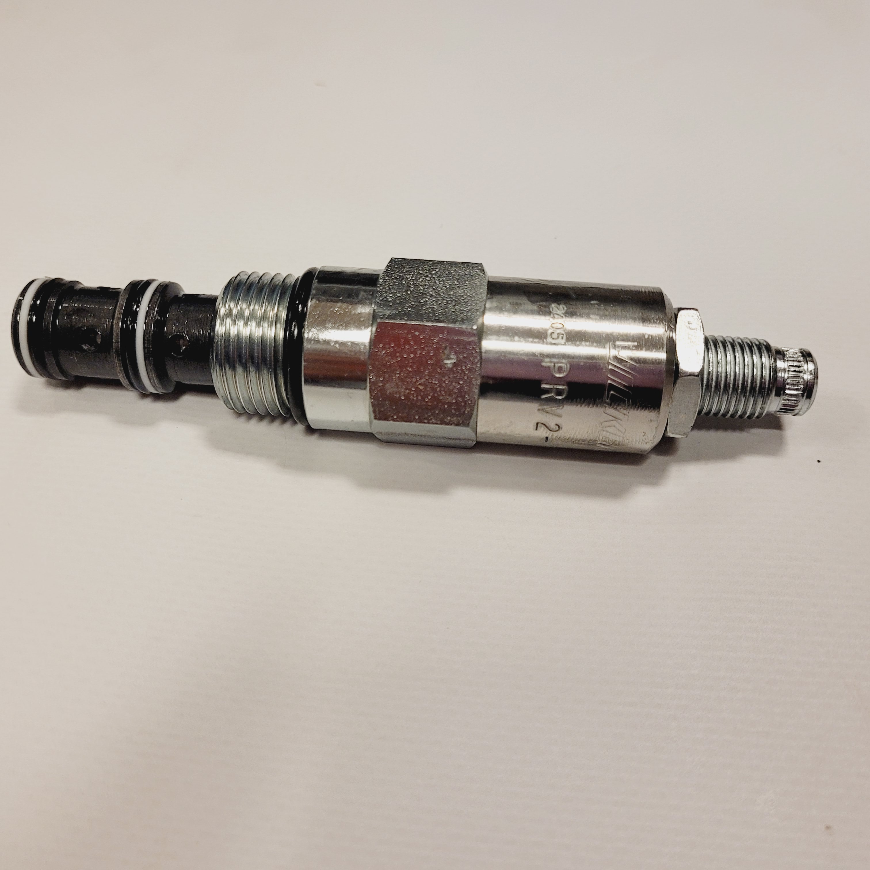
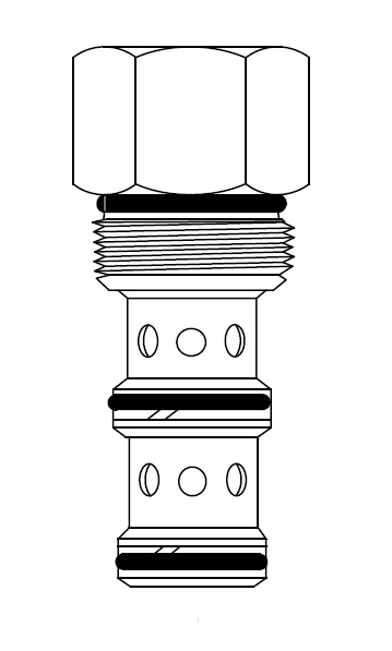
Pressure-control documentation includes Eaton RV1-10, RV3-10, RV5-10 and RV8-10 relief valves; PRV1-10, PRV2-10 and PRV12-10 reducing or reducing/relieving arrangements; and 1PSC30 sequence valves. Vented relief references include 1VR100 and 1VR150. Select each valve according to its full function, setting range, flow capacity and the circuit's pressure-control requirements.
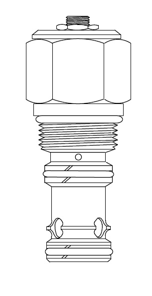
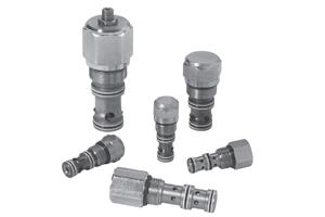
Logic elements can form part of combined or sequenced hydraulic functions. Referenced Eaton models include DPS2-10 and DPS2-8. Their behaviour depends on the surrounding circuit and pilot connections.
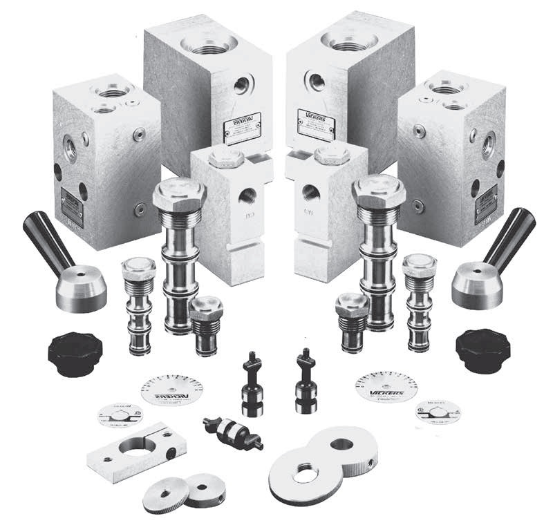
Referenced Eaton housings include size 10 models 02-175462, 876702, 876703 and 02-175102, and size 8 models 02-160727, 02-160728, 02-160733 and 02-160734. Associated accessories include adjustment knobs, orifices and check elements. Confirm the exact cavity, material and port configuration.
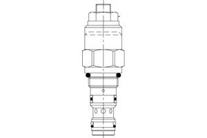
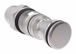
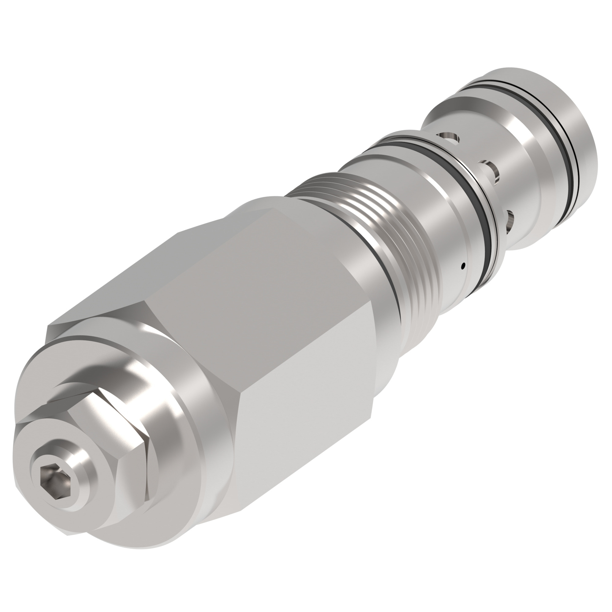
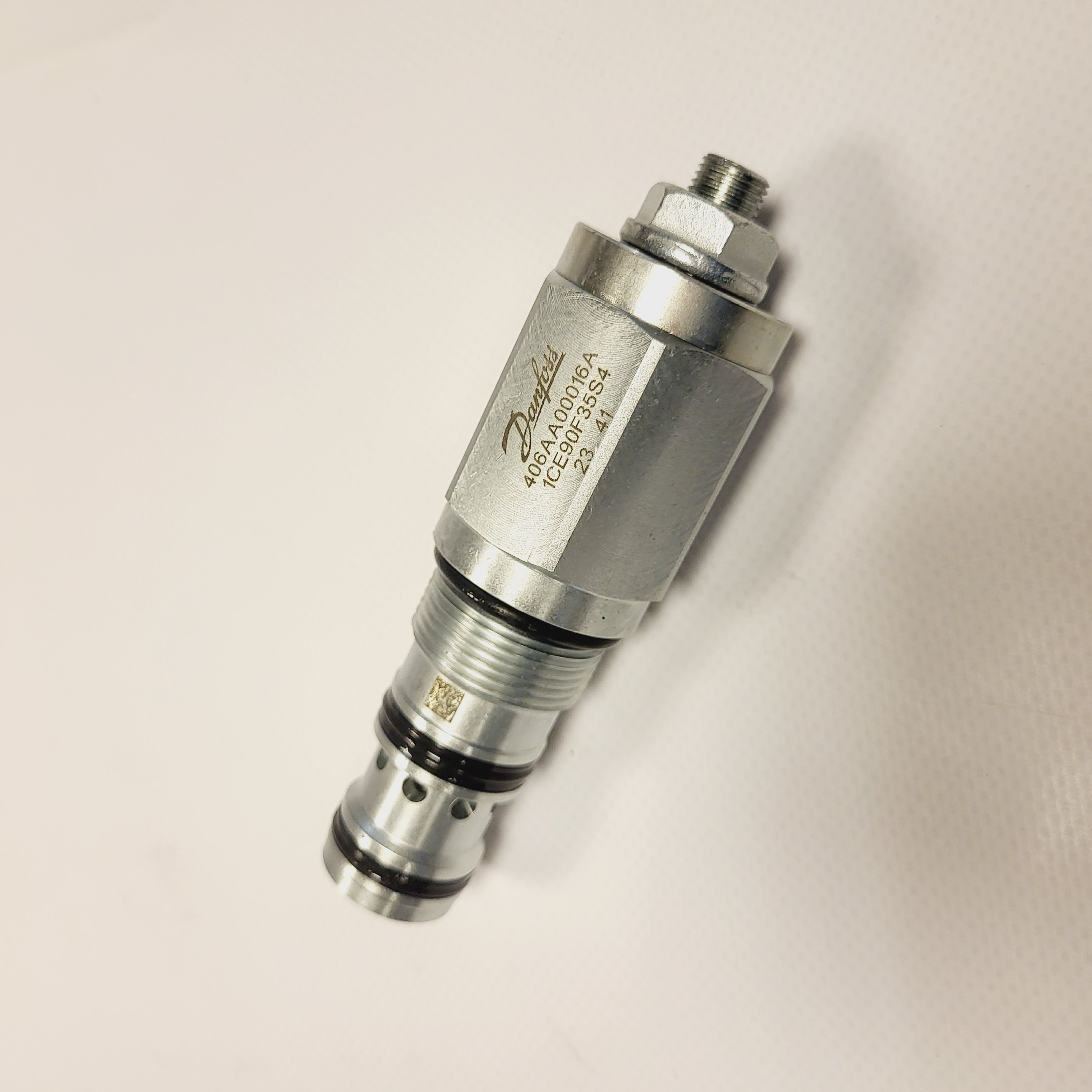
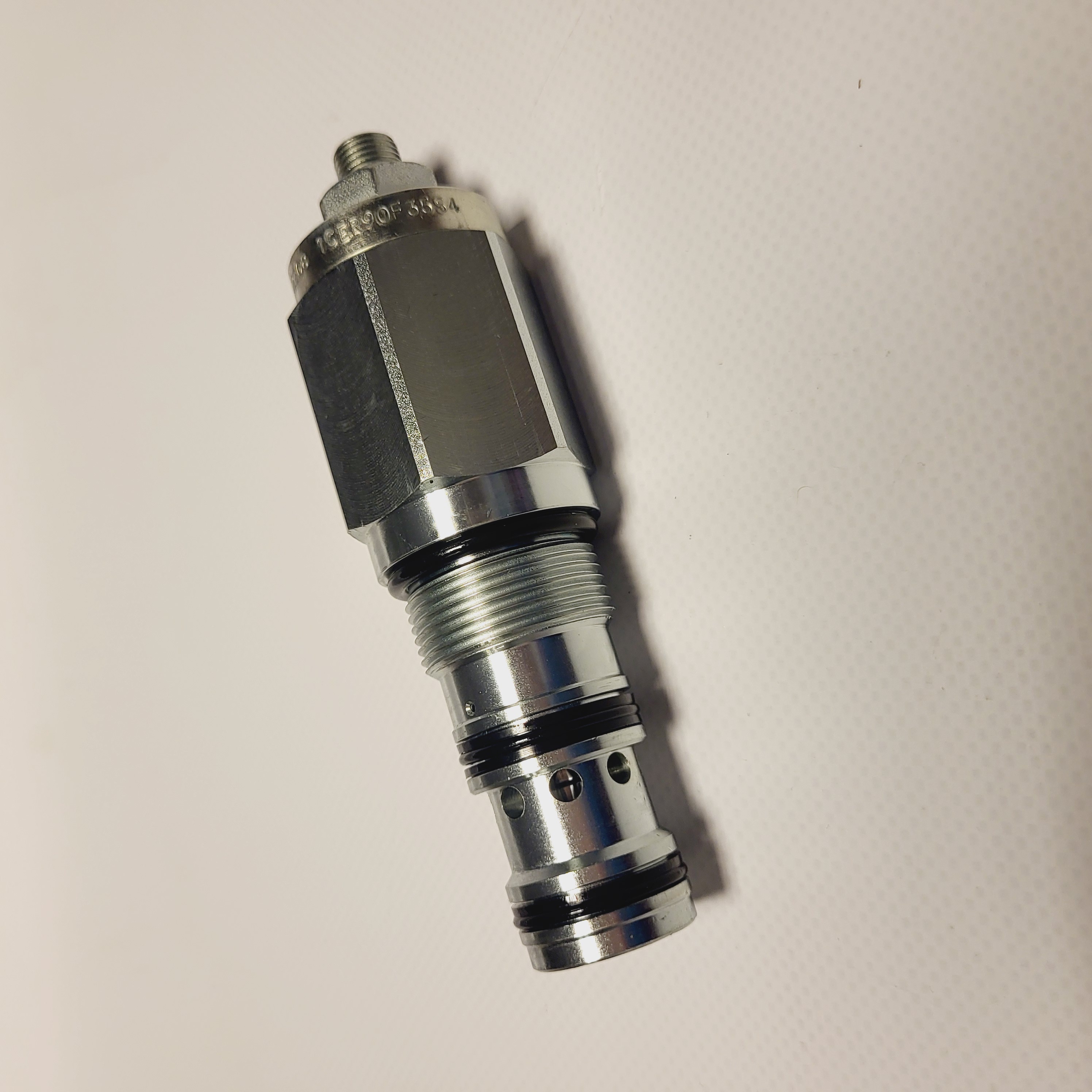
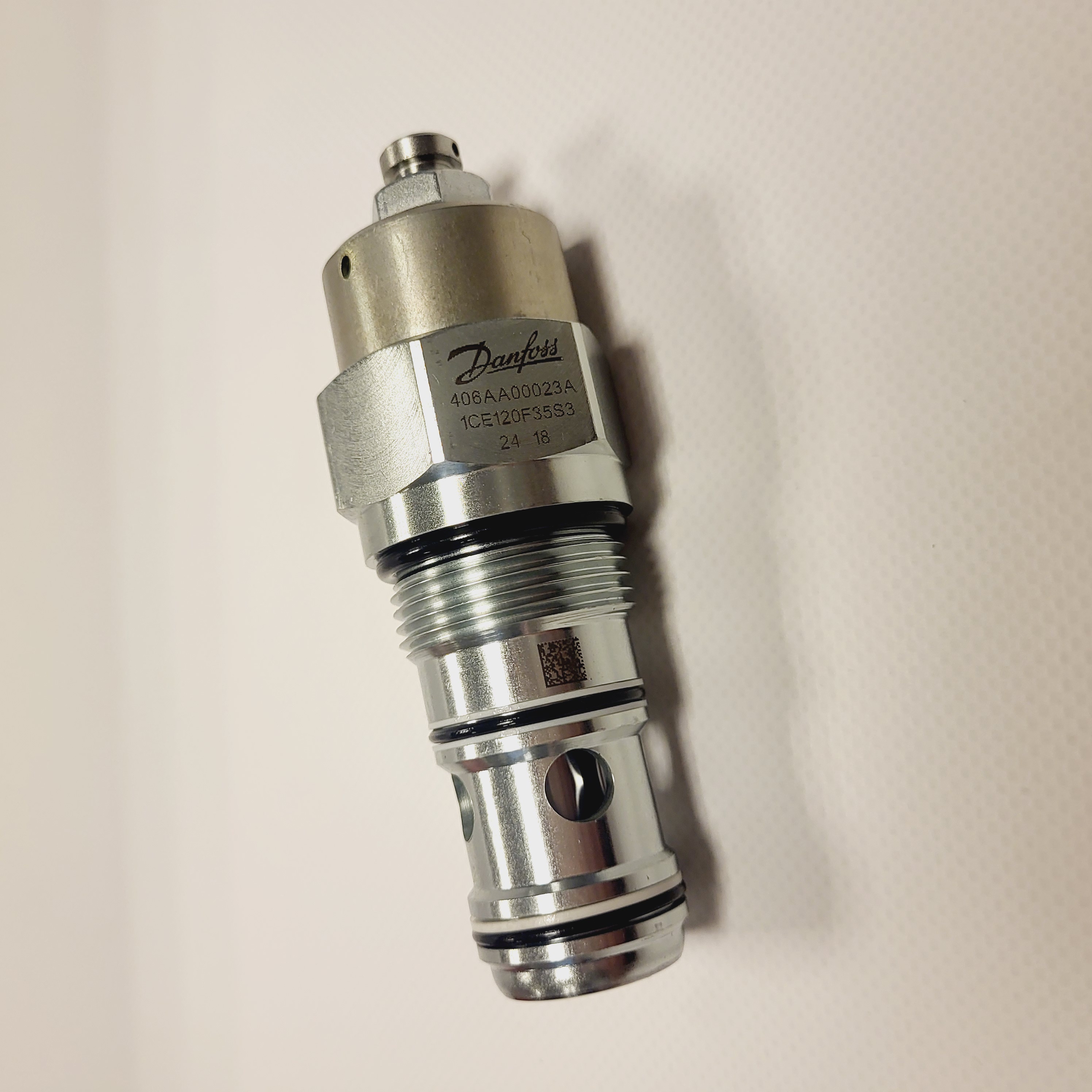
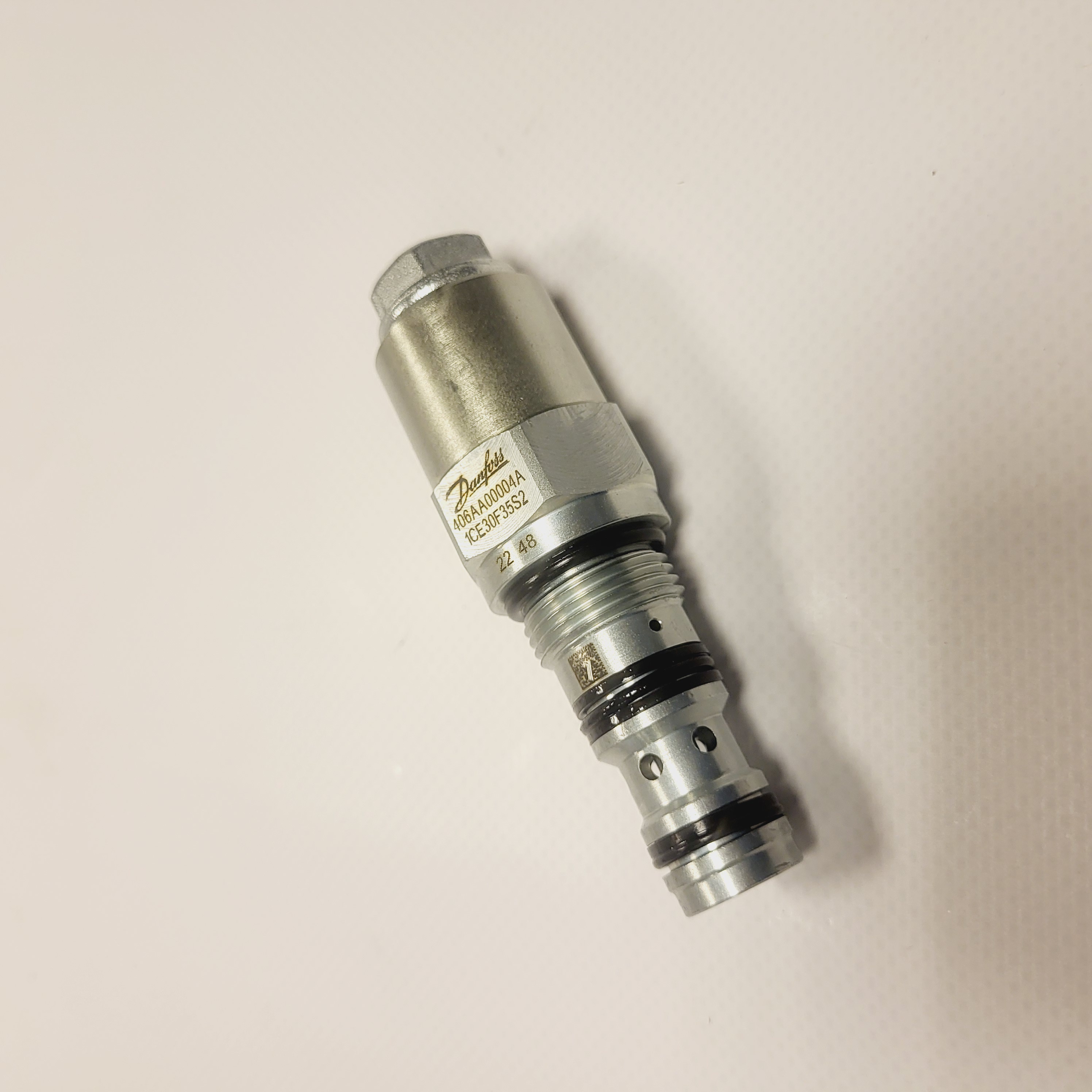
Eaton counterbalance documentation includes 1CE30, 1CE90 and 1CE120, along with 1CER, 1CEB and 1CEBD variants. Different venting and pressure-balancing arrangements affect circuit behaviour. Compare the full code, pilot ratio, setting and back-pressure sensitivity.
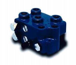
Eaton 39055-FAZ documentation covers a self-levelling valve assembly for suitable loader applications. Check the hydraulic circuit, cylinder arrangement and performance requirements before selection.
Eaton Vickers industrial slip-in cartridge valves and logic elements
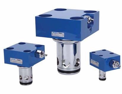
Eaton Vickers slip-in cartridge arrangements combine covers such as CVCS with elements such as CVI. Other referenced families include CVU and CVG. Functions and monitoring options depend on the selected cover, element and pilot circuit; confirm the complete assembly specification.
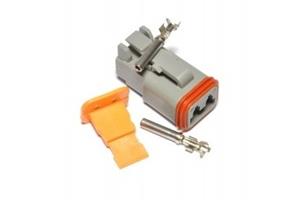
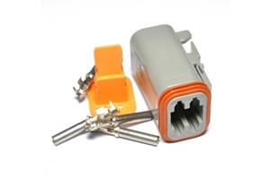
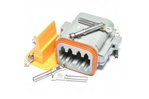
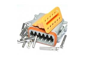
Deutsch female connectors: 2, 4, 8 and 12 pins
Deutsch connector references cover electrical connections used in suitable industrial and mobile applications. Environmental protection depends on the exact connector series, seals, cable sizes and correct assembly. Confirm the required ingress-protection rating in the component documentation; the connector name alone does not establish the rating of the complete installation.
What information should you prepare?
- Full designation, including all code suffixes.
- Function and hydraulic symbol.
- Cavity standard and housing configuration.
- Operating conditions and electrical control details, where applicable.
Send the part number and a description of the application. We will check the configuration against the relevant documentation.